|
|
Q.
Does the IG knob turn? (Is the keyless operation key recognised?)
|
|
|
 Replace the keyless operation key with which the IG knob does not turn (no recognition) and register the ID codes (Refer to Replace the keyless operation key with which the IG knob does not turn (no recognition) and register the ID codes (Refer to  ). ).
|
|
|
|
|
|
Refer to Inspection procedure 3 "Abnormality in KOS-ECU power supply and earth circuits" .
|
|
|
Q.
Is the check result normal?
|
|
|
 Repair the power supply circuit and the earth circuit to KOS-ECU. Repair the power supply circuit and the earth circuit to KOS-ECU.
|
|
|
|
|
|
Use M.U.T.-III to diagnose the CAN bus lines.
|
|
|
Q.
Is the check result normal?
|
|
|
Repair the CAN bus line (Refer to GROUP 54C - Troubleshooting ).
|
|
|
|
|
|
Check whether a KOS-related diagnosis code is set.
|
|
|
Q.
Is the diagnosis code set?
|
|
|
Refer to troubleshooting .
|
|
|
|
|
|
Check if "KOS feature" is set to "Both enable" or "ENG strt enable" with a customisation function of M.U.T.-III.
|
|
|
Q.
Is it set to "Both enable" or "ENG strt enable"?
|
|
|
Set "KOS feature" to "Both enable" or "ENG strt enable" with a customisation function of M.U.T.-III (Refer to ).
|
|
|
|
|
|
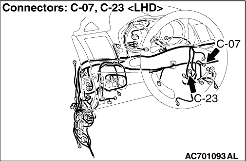
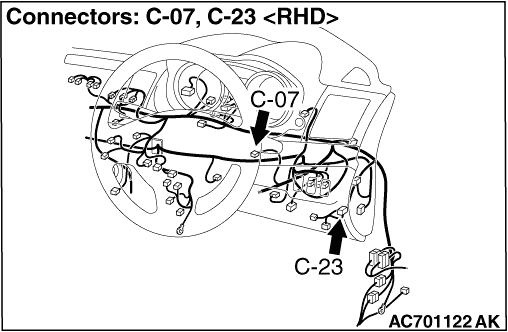
(1)Disconnect the KOS-ECU connector C-23.
|
|
|
(2)With the IG knob push switch pressed, measure the resistance at the harness-side connector.
|
|
|
(3)Resistance between the KOS-ECU connector C-23 terminal No. 8 and 34.
OK: Continuity exists (2 Ω or less)
|
|
|
Q.
Is the check result normal?
|
|
|
Check the C-23 KOS-ECU connector, the C-213 key reminder switch connector, the C-317 ETACS-ECU connector, and the wiring harness between the C-23 KOS-ECU connector (terminal No.8, 34) and the C-213 key reminder switch connector (terminal No.10, 4), and repair them if necessary. If they are normal, replace the key reminder switch.
|
|
|
|
|
|
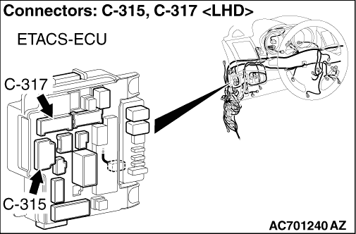
(1)Disconnect the C-315 ETACS-ECU connector.
|
|
|
(2)Measure the resistance at the harness-side connector with the ignition key removed from the ignition key cylinder.
|
|
|
(3)Check the continuity between the C-315 ETACS-ECU connector terminal No.13 and the earth.
OK: Continuity exists (2 Ω or less)
|
|
|
Q.
Is the check result normal?
|
|
|
Check the C-213 key reminder switch connector, the C-315 ETACS-ECU connector, the wiring harness between the C-213 key reminder switch connector (terminal No.3) and the C-315 ETACS-ECU connector (terminal No.13), and between the C-213 key reminder switch connector (terminal No.2) and the earth. If they are normal, replace the key reminder switch.
|
|
|
|
|
|
Q.
Is the check result normal?
|
|
|
Repair the defective connector.
|
|
|
|
|
|
Q.
Is the check result normal?
|
|
|
Repair the wiring harness.
|
|
|
|
|
|
(1)Disconnect receiver antenna module connector C-07 and measure the voltage available at the harness side of the connector.
|
|
|
(2)Measure the voltage between terminal No. 3 and earth.
OK: 5V
|
|
|
Q.
Is the check result normal?
|
|
|
Replace KOS-ECU and register the ID codes (Refer to ).
|
|
|
|
|
|
(1)Do not disconnect the receiver antenna module connector C-07.
|
|
|
(2)Connect an oscilloscope to receiver antenna module connector C-07 terminal No. 3 and earth by backprobing.
|

|
(3)Turn the ignition switch to the "LOCK" (OFF) position.
Q.
Is the waveform normal?
Go to Step 12.
Replace the receiver antenna module.
|
|
|
Check that the IG turns (keyless operation is recognised).
|
|
|
Q.
Is the check result normal?
|
|
|
The diagnosis is complete.
|
|
|
|
|
|
Replace KOS-ECU and register the ID codes (Refer to ).
|
|
|
|