|
|
1.Replace the following parts with new ones.
- SRS-ECU (Refer to
 ). ).
- Driver’s air bag module (Refer to ) <Except for RALLIART>, (Refer to ) <RALLIART>.
- Passenger’s (front) air bag module (Refer to ).
- knee air bag module (Refer to ).
- Seat belt with pre-tensioner (Refer to ).
- Front impact sensor (Refer to ).
- Instrument panel assembly (Refer to GROUP 52A - Instrument Panel Assembly ).
|
|
|
2.Check the following parts. If there is an abnormality, replace with new parts.
- Clock spring (Refer to ) <Except for RALLIART>, (Refer to ) <RALLIART>.
- Steering wheel, steering column assembly
- Check that the driver’s air bag module is installed to the steering wheel correctly.
- Check the steering wheel for noise, binding, operational failure, and play.
- Check the shock absorbing mechanism of steering column shaft assembly (Refer to GROUP 37 - On-vehicle Service <Hydraulic power steering>, <Electrical power steering).
|
|
|
3.Check the wiring harness for binding, the connector for damage, and the terminal for deformation (Refer to ).
|
|
|
1.Replace the following parts with new ones.
- SRS-ECU (Refer to ).
- Front seatback pad and frame assembly (Refer to ) <Except for RALLIART>, or front seatback (Refer to ).
- Curtain air bag module (Refer to ).
- Side impact sensor (Refer to ).
- Headlining (Refer to GROUP 52A, Headlining ).
- Front pillar trim, centre pillar trim upper, quarter trim upper (Refer to GROUP 52A - Interior Trim ).
|
|
|
2.Check the wiring harness for binding, the connector for damage, and the terminal for deformation (Refer to ).
|
|
|
1.Check the SRS air bag components and pre-tensioner according to the following procedures.
|
|
|
2.If a crack, deformation, or others are visually detected to the SRS air bag components or pre-tensioner, replace them with new parts.
|
|
|
3.Check the operation of seat belt. If the seat belt cannot be drawn out, replace the seat belt with a new one.
|
|
|
4.For removal and installation of parts, refer to "Servicing the SRS air bag/seat belt with pre-tensioner" .
|

|
1.Check the SRS-ECU case for dent, crack or deformation.
2.Check the connector and wiring harness for damage and the terminal for deformation.
3.Check that SRS-ECU is installed correctly.
|
|
|
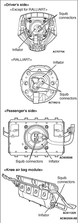
1.Check the pad cover for dent, crack or deformation.
|
|
2.Check the connector for damage, the terminal for deformation and the harness for binding.
3.Check the inflator case for dent, crack or deformation.
4.Check that the air bag module is installed correctly.
|

|
1.Check the connector and protector tube for damage and the terminal for deformation.
2.Check the case for damage.
3.Check the continuity between the connectors (Refer to ) <Except for RALLIART>, (Refer to ) <RALLIART>
|
|
|
1.Check that the driver’s air bag module is installed to the steering wheel correctly.
|
|
|
2.Check the steering wheel for noise, binding, operational failure and play.
|
|
|
3.Check the shock absorbing mechanism of steering column shaft assembly (Refer to GROUP 37 - On-vehicle Service <Hydraulic power steering>, <Electrical power steering).
|

|
1.Check the pre-tensioner for dent, crack or deformation.
2.Check the connector for damage and the terminal for deformation.
| note |
The illustration shows the pre-tensioner (RH). The position of the pre-tensioner (LH) is symmetrical to this.
|
|

|
1.Check the front impact sensor for dent, crack or deformation.
2.Check the connector for damage, the terminal for deformation and the harness for binding.
| note |
The illustration shows the front impact sensor (LH). The position of the front impact sensor (RH) is symmetrical to this.
|
|

|
1.Check that the side-airbag module deployment part of the seat is normal.
2.Check the connector for damage, the terminal for deformation and the harness for binding.
|
|
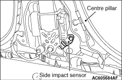
1.Check the centre pillar and quarter trim lower for deformation.
2.Check the side impact sensor for dent, crack, deformation or rust.
3.Check the connector for damage, the terminal for deformation and the harness for binding.
| note |
The illustration shows the side impact sensor (LH). The position of the side impact sensor (RH) is symmetrical to this.
|
|

|
1.Check that the curtain air bag deployment part of the headlining is normal.
2.Check the inflator surface for cracks, dents or deformations.
3.Check the connector for damage, the terminal for deformation and the harness for binding.
| note |
The illustration shows the curtain air bag module (RH). The position of the curtain air bag module (LH) is symmetrical to this.
|
|
|
|
Check the wiring harness for binding, the connector for damage and the terminal for deformation (Refer to ).
|