|
|
Using M.U.T.-III, perform CAN bus diagnosis (Refer to GROUP 54C - Explanation About The M.U.T-III Can Bus Diagnostics  ). ).
|
|
|
Q.
Is the check result satisfactory?
|
|
|
 Repair the CAN bus lines (Refer to GROUP 54C - Troubleshooting, Can Bus Diagnostic Table ). Then go to Step 15. Repair the CAN bus lines (Refer to GROUP 54C - Troubleshooting, Can Bus Diagnostic Table ). Then go to Step 15.
|
|
|
|
|
|
Using M.U.T.-III, check the data list.
|
|
|
- Item 74: Stop lamp switch
|
|
|
(Refer to data list reference table ) <BSY>.
|
|
|
Q.
Is the check result normal?
|
|
|
Using M.U.T.-III, check the ETACS system data list (Refer to GROUP 54A - ETACS, data list reference table ).
|
|
|
Q.
Is the check result normal?
|
|
|
 Replace the engine-ECU (Refer to GROUP 13A - Engine-ECU ). Then go to Step 15. Replace the engine-ECU (Refer to GROUP 13A - Engine-ECU ). Then go to Step 15.
|
|
|
|
|
|
Q.
Is the check result normal?
|
|
|
Repair or replace the damaged components. Then go to Step 15.
|
|
|
|
|
|
Q.
Is the check result normal?
|
|
|
Repair the damaged harness wire. Then go to Step 15.
|
|
|
|
|
|
(1)Remove the stop lamp switch (Refer to GROUP 35A - Brake Pedal ).
|
|
|
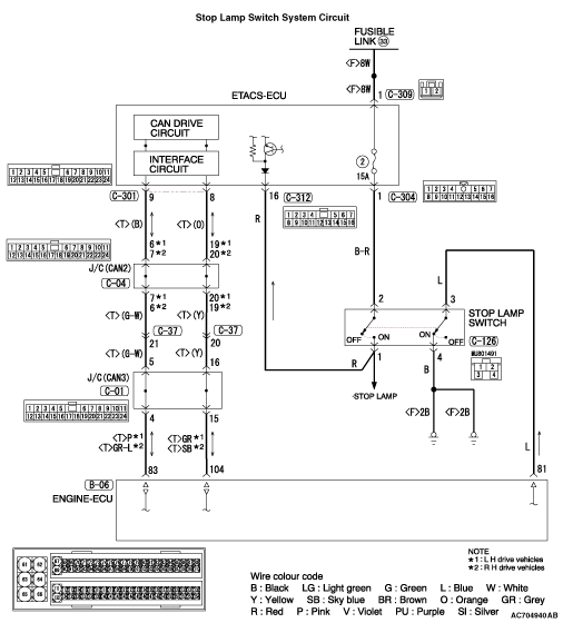
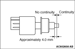
(2)Connect an ohmmeter to the stop lamp switch between terminals No. 1 and No. 2.
|
|
(3)Check for continuity between the terminals when the plunger of the stop lamp switch is pushed in and when it is released.
OK: The stop lamp switch is operating properly if the circuit is open between terminals No. 1 and No. 2 when the plunger is pushed in to a depth of within approximately 4.0 mm from the outer case edge surface, and if the resistance value is less than 2 ohms between terminals No. 1 and No. 2 when it is released.
Q.
Is the check result normal?
Install the stop lamp switch (Refer to GROUP 35A - Brake Pedal ). Then go to Step 7.
Replace the stop lamp switch (Refer to GROUP 35A - Brake Pedal ). Then go to Step 15.
|
|
|
Q.
Is the fuse in good condition?
|
|
|
Check the stop lamp system harness and replace the fuse. Then go to Step 15.
|
|
|
|
|
|
Using M.U.T.-III, check the ETACS system data list (Refer to GROUP 54A - ETACS, data list reference table ).
|
|
|
Q.
Is the check result normal?
|
|
|
It can be assumed that this malfunction is intermittent (Refer to GROUP 00 - How to Use Troubleshooting/Inspection Service Points, How to Cope with Intermittent Malfunction ).
|
|
|
|
|
|
Replace the ETACS-ECU (Refer to GROUP 54A - ETACS, ETACS-ECU ). Then go to Step 15.
|
|
|
|
|
|
Using M.U.T.-III, check the data list .
|
|
|
(Refer to data list reference table ) <BSY>.
|
|
|
Q.
Is the check result normal?
|
|
|
Q.
Is the check result normal?
|
|
|
Repair or replace the damaged connectors. Then go to Step 15.
|
|
|
|
|
|
Q.
Is the check result normal?
|
|
|
Repair the damaged harness wire. Then go to Step 15.
|
|
|
|
|
|
(1)Remove the stop lamp switch (Refer to GROUP 35A - Brake Pedal ).
|
|
|
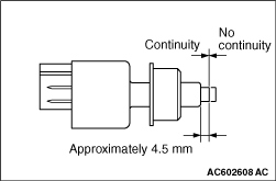
(2)Connect an ohmmeter to the stop lamp switch between terminals No. 3 and No. 4.
|
|
(3)Check for continuity between the terminals when the plunger of the stop lamp switch is pushed in and when it is released.
OK: The stop lamp switch is operating properly if the circuit is open between terminals No. 3 and No. 4 when the plunger is released, and if resistance value is less than 2 ohms between terminals No. 3 and No. 4 when the plunger is pushed in to a depth of within approximately 4.5 mm from the outer case edge surface.
Q.
Is the check result normal?
Install the stop lamp switch (Refer to GROUP 35A - Brake Pedal ). Then go to Step 13.
Replace the stop lamp switch (Refer to GROUP 35A - Brake Pedal ). Then go to Step 15.
|
|
|
Using M.U.T.-III, check the data list .
|
|
|
(Refer to data list reference table ) <BSY>.
|
|
|
Q.
Is the check result normal?
|
|
|
It can be assumed that this malfunction is intermittent (Refer to GROUP 00 - How to Use Troubleshooting/Inspection Service Points, How to Cope with Intermittent Malfunction ).
|
|
|
|
|
|
Replace the engine-ECU (Refer to GROUP 13A - Engine-ECU ). Then go to Step 15.
|
|
|
|
|
|
Using M.U.T.-III, read the diagnosis code of the cruise control system (Refer to ).
|
|
|
Q.
Is diagnosis code P0504 or P0573 set?
|
|
|
Replace the engine-ECU (Refer to GROUP 13A - Engine-ECU ). Then go to Step 15.
|
|
|
|
|
|
It can be assumed that this malfunction is intermittent (Refer to GROUP 00 - How to Use Troubleshooting/Inspection Service Points, How to Cope with Intermittent Malfunction ).
|
|
|
|
|
|
Using M.U.T.-III, check the data list .
|
|
|
- Item 74: Stop lamp switch
- Item 89: Brake switch
|
|
|
(Refer to data list reference table ) <BSY>.
|
|
|
Q.
Is the check result normal?
|
|
|
Using M.U.T.-III, read the diagnosis code of the cruise control system (Refer to ).
|
|
|
Q.
Is diagnosis code P0504 or P0573 set?
|
|
|
The procedure is complete.
|
|
|
|