|
|
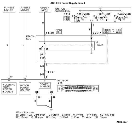
- The ASC-ECU power supply signal energised by the ignition
switch (IG1) is transmitted to ASC-ECU (terminal No.4) via the multi-purpose fuse No.12.
- The ASC-ECU power supply and the valve power supply are transmitted to ASC-ECU (terminal
No.32) via the fusible link No.27.
- The ASC-ECU power supply and the valve power supply are transmitted to ASC-ECU (terminal
No.1) via the fusible link No.26.
- When malfunction occurs in ASC-ECU power supply, the communication with M.U.T.-III
becomes unavailable.
|
|
|
- Damaged wiring harness and connectors
- Battery failure
- Charging system failed
- ASC-ECU malfunction
|
|
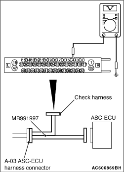
(1)Disconnect the ASC-ECU connector, connect special tool ASC check harness (MB991997) to
the harness-side connector, and then measure the voltage at the special tool connector side.
| note |
Do not connect the special tool ASC check harness (MB991997) to ASC-ECU.
|
(2)Turn the ignition switch to the ON position.
(3)Measure the voltage between terminal No.4 and body earth.
OK: Approximately battery voltage
Q.
Is the check result normal?
 Go to Step 2. Go to Step 2.
 Go to Step 8. Go to Step 8.
|

|
(1)Disconnect the ASC-ECU connector, connect special tool ASC check harness (MB991997) to
the harness-side connector, and then measure the voltage at the special tool connector side.
| note |
Do not connect the special tool ASC check harness (MB991997) to ASC-ECU.
|
(2)Measure the voltage between the terminal No.32 and the body earth.
OK: Approximately battery voltage
Q.
Is the check result normal?
Go to Step 5.
Go to Step 3.
|
|
|
Q.
Is the check result normal?
|
|
|
Replace the fusible link No.27.
|
|
|
|
|
|
Q.
Is the check result normal?
|
|
|
Repair the wiring harness between the fusible link No.27 and the A-03 ASC-ECU
connector terminal No.32.
|
|
|
|
|
|
Repair the defective connector.
|
|
|
|

|
(1)Disconnect the ASC-ECU connector, connect special tool ASC check harness (MB991997) to
the harness-side connector, and then measure the voltage at the special tool connector side.
| note |
Do not connect the special tool ASC check harness (MB991997) to ASC-ECU.
|
(2)Voltage between the terminal No.1 and the body earth
OK: Approximately battery voltage
Q.
Is the check result normal?
Go to Step 17.
Go to Step 6.
|
|
|
Q.
Is the check result normal?
|
|
|
Replace the fusible link No.26.
|
|
|
|
|
|
Q.
Is the check result normal?
|
|
|
Repair the wiring harness between the fusible link No.26 and the A-03 ASC-ECU
connector terminal No.1.
|
|
|
|
|
|
Repair the defective connector.
|
|
|
|
|
|
Q.
Is the check result normal?
|
|
|
Replace the abnormal fuse or fusible link.
|
|
|
|
|
|
Q.
Is the check result normal?
|
|
|
Repair the defective connector.
|
|
|
|
|
|
(1)Disconnect the ETACS-ECU connector, and then measure the voltage at the harness
connector side.
|
|
|
(2)Voltage between the terminal No.1 and the body earth
OK: Approximately battery voltage
|
|
|
Q.
Is the check result normal?
|
|
|
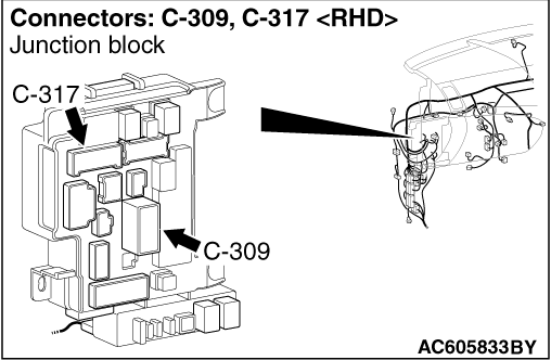
Repair the wiring harness between the fusible link No.33 and the C-309 ETACS-ECU
connector terminal No.1.
|
|
|
|
|
|
Q.
Is the check result normal?
|
|
|
Repair the defective connector.
|
|
|
|
|
|
(1)Disconnect the ETACS-ECU connector, and then measure the voltage at the ETACS-ECU
side.
|
|
|
(2)Turn the ignition switch to the ON position.
|
|
|
(3)Voltage between the terminal No.6 and the body earth
OK: Approximately battery voltage
|
|
|
Q.
Is the check result normal?
|
|
|
Q.
Is the check result normal?
|
|
|
Repair the wiring harness between the C-210 ignition switch connector terminal
No.2 and the C-317 ETACS-ECU connector terminal No.6.
|
|
|
|
|
|
(1)Disconnect the A-04 ABS-ECU connector, and then measure the voltage at the ETACS-ECU
connector to the backprobing.
|
|
|
(2)Turn the ignition switch to the ON position.
|
|
|
(3)Voltage between the terminal No.5 and the body earth
OK: Approximately battery voltage
|
|
|
Q.
Is the check result normal?
|
|
|
Replace ETACS-ECU (Refer to GROUP 54A - ETACS-ECU  ). ).
|
|
|
|
|
|
Q.
Is the check result normal?
|
|
|
Repair the defective connector.
|
|
|
|
|
|
- Check for open or short circuit.
|
|
|
Q.
Is the check result normal?
|
|
|
Repair the wiring harness.
|
|
|
|

|
(1)Disconnect the ASC-ECU connector, connect special tool ASC check harness (MB991997) to
the harness-side connector, and then measure the resistance at the special tool connector side.
| note |
Do not connect the special tool ASC check harness (MB991997) to ASC-ECU.
|
(2)Resistance between terminal No.16 and body earth, and between terminal No.47 and
body earth.
OK: Continuity exists (2 Ω or less)
Q.
Is the check result normal?
Go to Step 18.
Repair the wiring harness.
|
|
|
Refer to GROUP 54A - Battery Test .
|
|
|
Q.
Is the battery in good condition?
|
|
|
Charge or replace the battery.
|
|
|
|
|
|
Refer to GROUP 16 - Charging System (2000), (2200), (2400)
or (3000).
|
|
|
Q.
Is the charging system in good condition?
|
|
|
Repair or replace the charging system component(s).
|
|
|
|
|
|
Q.
Is the communication with M.U.T.-III possible?
|
|
|
Intermittent malfunction (Refer to GROUP 00 - How to Cope with Intermittent
Malfunction ).
|
|
|
|
|
|
Make sure that the M.U.T.-III cable is properly connected and the V.C.I. switch
is ON, and then replace the ASC-ECU (Refer to ).
|
|
|
|