Inspection Procedure 4: The Navigation System can be Operated while the Vehicle is Driven.
| caution | Before replacing the multivision display, ensure that the power supply circuit, the earth circuit, and the communication circuit are normal. (Check that the voltage is 10 V or more.) |
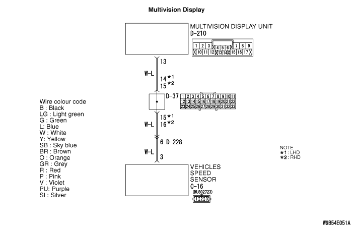





COMMENTS ON TROUBLE SYMPTOM
PROBABLE CAUSES
- Malfunctions of combination meter
- Malfunctions of multivision display
- Damaged harness wires and connectors
DIAGNOSIS PROCEDURE |
STEP 1. Perform "Vehicle Signal Check" in the MMCS service mode. |
Perform "Vehicle Signal Check" in the MMCS service mode to check whether vehicle speed signal is normal. (Refer to  .) .) |
Q.
Is the vehicle speed signal transmitted normally?
|
 Replace the multivision display. Replace the multivision display. |
|
 Go to Step 2. Go to Step 2. |
|
STEP 2. Check the speedometer. |
| Check whether the speedometer works normally.(Refer to .) |
Q.
Does the speedometer work normally?
|
| Go to Step 3. |
|
| Diagnose the combination meter. (Refer to Combination meter - Troubleshooting .) |
|
STEP 3. Connector check: C-16 vehicle speed sensor connector, D-210 multivision display connector |
Q.
Is the check result normal?
|
| Go to Step 4. |
|
| Repair the defective connector. |
|
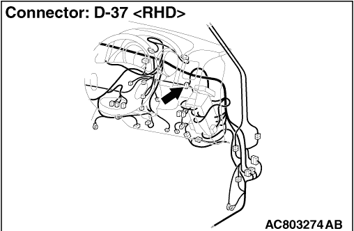
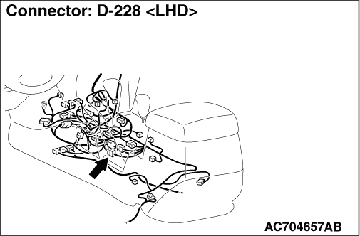
STEP 4. Check the wire harness between C-16 vehicle speed sensor connector terminal No.3 and D-210 multivision display connector terminal No.13. |
|
|
Q.
Is the check result normal?
|
| Go to Step 5. |
|
| Repair the wiring harness. |
|
STEP 5. Substitute a known good multivision display, and check the trouble symptom. |
| Check that no menus are active during driving. |
Q.
Is the check result normal?
|
| Replace the multivision display. |
|
| Replace the combination meter. |
|