REMOVAL AND INSTALLATION


caution
  • The reinstallation histories of the removed fuel injection pipe and fuel supply pipe assembly are up to five times. To count how many times the fuel injection pipe and fuel supply pipe assembly is reinstalled, record the number of the reinstallation histories on the service booklet by adding this latest number of the histories, which is usually "1", to the previous one. Use a new fuel injection pipe and fuel supply pipe assembly when the total reinstallation history numbers reach five times, or when the supply pump assembly or common rail assembly is replaced. In this case, record "a new fuel injection pipe and fuel supply pipe assembly, the number of the reinstallation histories is zero" on the service booklet.
  • If a fuel leak is present in the fuel injection pipe and fuel supply pump pipe once, do not reuse it and replace with a new one.
  • If the fuel injector assembly, common rail assembly or supply pump assembly is replaced, the contact surface (seal surface) between the fuel injection pipe and fuel supply pump pipe, and the other side component is changed, do not reuse the fuel injection pipe and fuel supply pump pipe and replace with a new one.
  • When the fuel injection pipe and fuel supply pipe assembly is reinstalled, confirm there is no foreign material on the seal surface or in the pipe and then install it not to deviate from the axis, fitting the seal surface.
  • When the injector assembly is replaced, register the injector identification code and perform the fuel injection learning (Refer to GROUP 00 - Precautions Before Service, What The Common Rail Engine Learns ).
Pre-removal Operation
  • Engine Cover Removal (Refer to GROUP 11C - Engine Assembly ).
  • Battery and Battery Tray Removal (Refer to GROUP 54A - Battery ).

Post-installation Operation
  • Battery and Battery Tray Installation (Refer to GROUP 54A - Battery ).
  • Fuel Line Leak Check (Refer to ).
  • Engine Cover Installation (Refer to GROUP 11C - Engine Assembly ).


<Except emission regulation Euro 5>


Common rail assembly and Injector assembly removal steps


1.
Breather hose


·
A/T fluid level gauge guide assembly <A/T> (Refer to GROUP 23C - Transmission Assembly ).


·
Engine oil level gauge guide (Refer to GROUP 11C - Oil Pan and Oil Strainer ).


2.
Fuel hose


3.
Fuel return hose


4.
Fuel return B pipe assembly
<<A>>
>>D<<
5.
Fuel supply pump pipe assembly


·
Air inlet pipe (Refer to GROUP 15 - Inlet Manifold ).

>>D<<
6.
Injection pipe clamp

>>D<<
7.
Injection pipe clamp
<<B>>
>>D<<
8.
Fuel injection No.4 pipe assembly
<<B>>
>>D<<
9.
Fuel injection No.3 pipe assembly
<<B>>
>>D<<
10.
Fuel injection No.2 pipe assembly
<<B>>
>>D<<
11.
Fuel injection No.1 pipe assembly


12.
Rail pressure sensor connector connection


13.
Harness clamp
<<C>>
>>D<<
14.
Common rail assembly

>>D<<
15.
Gasket

>>D<<
16.
Fuel pipe bracket

>>D<<
17.
Fuel return A pipe assembly

>>D<<
18.
Gasket


19.
Injector assembly connector connection


20.
Solenoid valve connector connection <Emission regulation Euro 4>


21.
Vacuum hose connection <Emission regulation Euro 4>


22.
Solenoid valve assembly <Emission regulation Euro 4


23.
E-VRV connector connection


24.
Vacuum hose connection


25.
E-VRV assembly


26.
E-VRV bracket


27.
Rocker cover assembly


28.
Rubber assembly

>>C<<
29.
Oil seal

>>B<<
30.
Oil seal


31.
Harness bracket


32.
Rocker cover gasket

>>A<<
33.
Fuel leakage pipe assembly

>>A<<
34.
Gasket

>>A<<
35.
Injection holder bolt

>>A<<
36.
Injector supporter

>>A<<
37.
Support bolt

>>A<<
38.
Injector assembly


39.
Gasket


40.
Pivot boss


41.
Pivot bar


Fuel supply pump pipe assembly and fuel injection pipe assembly removal steps
<<A>>
>>E<<
5.
Fuel supply pump pipe assembly


·
Air inlet pipe (Refer to GROUP 15 - Inlet Manifold ).

>>E<<
6.
Injection pipe clamp

>>E<<
7.
Injection pipe clamp
<<B>>
>>E<<
8.
Fuel injection No.4 pipe assembly
<<B>>
>>E<<
9.
Fuel injection No.3 pipe assembly
<<B>>
>>E<<
10.
Fuel injection No.2 pipe assembly
<<B>>
>>E<<
11.
Fuel injection No.1 pipe assembly

<Emission regulation Euro 5>


Common rail assembly and Injector assembly removal steps


1.
Breather hose


·
A/T fluid level gauge guide assembly <A/T> (Refer to GROUP 23C - Transmission Assembly ).


·
Engine oil level gauge guide (Refer to GROUP 11C - Oil Pan and Oil Strainer ).


2.
Fuel hose


3.
Fuel return hose


4.
Fuel return B pipe assembly
<<A>>
>>D<<
5.
Fuel supply pump pipe assembly


·
Air inlet pipe (Refer to GROUP 15 - Inlet Manifold ).

>>D<<
6.
Injection pipe clamp

>>D<<
7.
Injection pipe clamp
<<B>>
>>D<<
8.
Fuel injection No.4 pipe assembly
<<B>>
>>D<<
9.
Fuel injection No.3 pipe assembly
<<B>>
>>D<<
10.
Fuel injection No.2 pipe assembly
<<B>>
>>D<<
11.
Fuel injection No.1 pipe assembly


12.
Rail pressure sensor connector connection


13.
Harness clamp
<<C>>
>>D<<
14.
Common rail assembly

>>D<<
15.
Gasket

>>D<<
16.
Fuel pipe bracket

>>D<<
17.
Fuel return A pipe assembly

>>D<<
18.
Gasket


19.
Injector assembly connector connection


20.
Solenoid valve connector connection


21.
Vacuum hose connection


22.
Solenoid valve assembly


23.
E-VRV connector connection


24.
Vacuum hose connection


25.
E-VRV assembly


26.
E-VRV bracket


27.
No.1 exhaust gas temperature sensor connector connection <M/T>


28.
Harness bracket <M/T>


29.
EGR cooler bypass valve solenoid valve connector connection


30.
Vacuum hose connection


31.
EGR cooler bypass valve solenoid valve


32.
Rocker cover assembly


33.
Rubber assembly

>>C<<
34.
Oil seal

>>B<<
35.
Oil seal


36.
Harness bracket


37.
Rocker cover gasket

>>A<<
38.
Fuel leakage pipe assembly

>>A<<
39.
Gasket

>>A<<
40.
Injection holder bolt

>>A<<
41.
Injector supporter

>>A<<
42.
Support bolt

>>A<<
43.
Injector assembly


44.
Gasket


45.
Pivot boss


46.
Pivot bar


Fuel supply pump pipe assembly and fuel injection pipe assembly removal steps
<<A>>
>>E<<
5.
Fuel supply pump pipe assembly


·
Air inlet pipe (Refer to GROUP 15 - Inlet Manifold ).

>>E<<
6.
Injection pipe clamp

>>E<<
7.
Injection pipe clamp
<<B>>
>>E<<
8.
Fuel injection No.4 pipe assembly
<<B>>
>>E<<
9.
Fuel injection No.3 pipe assembly
<<B>>
>>E<<
10.
Fuel injection No.2 pipe assembly
<<B>>
>>E<<
11.
Fuel injection No.1 pipe assembly

REMOVAL SERVICE POINTS


<<A>> FUEL SUPPLY PUMP PIPE ASSEMBLY REMOVAL


caution Because the fuel pressure in the fuel line is high, wait for 3 minutes or longer after the engine is stopped. Then, cover the fuel supply pump pipe with a rag or similar materials to prevent the fuel spill, and then disconnect the fuel supply pump pipe assembly.

<<B>> FUEL INJECTION NO.4 PIPE ASSEMBLY/FUEL INJECTION NO.3 PIPE ASSEMBLY/FUEL INJECTION NO.2 PIPE ASSEMBLY/FUEL INJECTION NO.1 PIPE ASSEMBLY REMOVAL


Using special tool fuel injection pipe wrench (MB992188), remove the fuel injection pipe assembly No.1 to No.4.

<<C>> COMMON RAIL ASSEMBLY REMOVAL


caution
  • When operating, do not support the common rail assembly by holding the rail pressure limiter and the pressure sensor at both ends.
  • Before the installation, make sure that there is no foreign object or rust to the thread and to the high-pressure pipe sheet surface.

INSTALLATION SERVICE POINTS


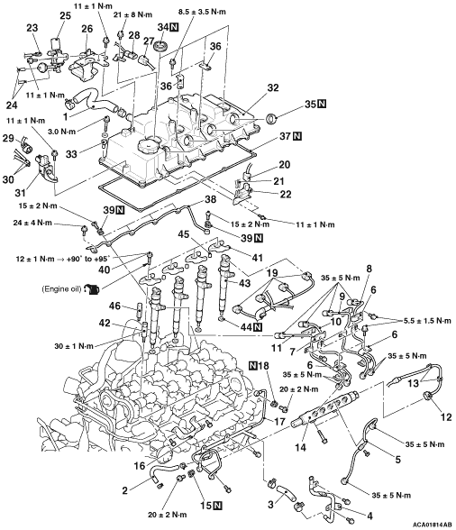
>>A<< INJECTOR ASSEMBLY/ SUPPORT BOLT/INJECTOR SUPPORT/INJECTOR HOLDER BOLT/GASKET/FUEL LEAKAGE PIPE ASSEMBLY INSTALLATION


1.Tighten the support bolts to the specified torque.
Tightening torque: 30 ± 1 N·m
2.Install the gasket, injector assembly and pivot boss.

3.Apply the engine oil to the bearing surface and thread of injector holder bolts.
4.Temporarily fix the injector supporters.
5.Install the gaskets to the fuel leakage pipe assembly.
6.Tighten the eye bolts at the Injector assembly side to the specified torque.
Tightening torque: 15 ± 2 N·m
7.Tighten the eye bolt at the cylinder head side to the specified torque.
Tightening torque: 15 ± 2 N·m
8.Tighten the fuel leakage pipe assembly mounting bolt to the specified torque.
Tightening torque: 24 ± 4 N·m

9.Tighten the injector holder bolts according to the following procedure.
(1) Tighten the Injector holder bolts to 12 ± 1 N·m.
(2)
caution
  • If the bolt is tightened less than the specified lower limit of 90 degree angle, the bolt may become loose. Be sure to tighten correctly.
  • If the bolt is tightened in excess of the specified upper limit of 95 degree angle, loosen the bolt completely and repeat the entire procedures.
Using special tool angle gauge (MB991614), tighten the Injector holder bolts in the illustrated sequence by a further 90 to 95 degree angle.

>>B<< OIL SEAL INSTALLATION


1.Using a proper socket wrench, the oil seal is pressed and fit into the rocker cover.

>>C<< OIL SEAL INSTALLATION


Use special tools oil seal installer (MB992104) and handle (MB992075) to press-fit the oil seal.

>>D<< GASKET/FUEL RETURN A PIPE ASSEMBLY/FUEL PIPE BRACKET/COMMON RAIL ASSEMBLY/FUEL INJECTION NO.1 PIPE ASSEMBLY/FUEL INJECTION NO.2 PIPE ASSEMBLY/FUEL INJECTION NO.3 PIPE ASSEMBLY/FUEL INJECTION NO.4 PIPE ASSEMBLY/INJECTOR PIPE CLAMP/FUEL SUPPLY PUMP PIPE ASSEMBLY INSTALLATION


caution
  • The reinstallation histories of the removed fuel injection pipe and fuel supply pipe assembly are up to five times. To count how many times the fuel injection pipe and fuel supply pipe assembly is reinstalled, record the number of the reinstallation histories on the service booklet by adding this latest number of the histories, which is usually "1", to the previous one. Use a new fuel injection pipe and fuel supply pipe assembly when the total reinstallation history numbers reach five times, or when the supply pump assembly or common rail assembly is replaced. In this case, record "a new fuel injection pipe and fuel supply pipe assembly, the number of the reinstallation histories is zero" on the service booklet.
  • If a fuel leak is present in the fuel injection pipe and fuel supply pump pipe once, do not reuse it and replace with a new one.
  • If the fuel injector assembly, common rail assembly or supply pump assembly is replaced, the contact surface (seal surface) between the fuel injection pipe and fuel supply pump pipe, and the other side component is changed, do not reuse the fuel injection pipe and fuel supply pump pipe and replace with a new one.
  • When the fuel injection pipe and fuel supply pipe assembly is reinstalled, confirm there is no foreign material on the seal surface or in the pipe and then install it not to deviate from the axis, fitting the seal surface.
1.Install and temporarily fix the gaskets to the fuel return A pipe assembly.
2.Using the eye bolt, tighten the cylinder head side of fuel return A pipe assembly to the specified torque.
Tightening torque: 20 ± 2 N·m

3.
caution
  • When operating, do not support the common rail assembly by holding the pressure limiter and the rail pressure sensor at both ends.
  • Before the installation, make sure that there is no foreign object or rust to the thread and to the high-pressure pipe sheet surface.
Temporarily fix the common rail assembly.
4.Align the fuel injection pipe centre axis with the other side components (fuel injector assembly and common rail assembly) centre axis to install the fuel injection pipe. Then, tighten the flare nut temporarily until the tip of pipe (seal surface) contacts with the other side components.
note When the fuel injection pipe is installed, tighten the flare nut while shaking the pipe lightly to align the centre axis of both components.


5.Using special tool fuel injection pipe wrench (MB992188), start tightening the fuel injector assembly side flare nut in the fuel injection pipe, and then tighten the fuel injector assembly side flare nut and common rail assembly side flare nut alternately in several steps to the specified torque.
Tightening torque: 35 ± 5 N·m
note When there is a fear that a bruise is put, wind sealing tape around the fuel injection pipe, to prevent damage.
6.Using the bolt, tighten the common rail assembly side of fuel return pipe to the specified torque.
Tightening torque: 20 ± 2 N·m
7.Tighten the common rail assembly mounting bolt to the standard torque.
8.Tighten the bolt of the inlet manifold installation point of the fuel return pipe to the standard torque.
9.Install the fuel return pipe bracket.
10.Tighten the bolt of the fuel return pipe bracket installation point of the fuel return pipe to the standard torque.
11.Install the inlet manifold air inlet fitting (Refer to GROUP 15 - Inlet Manifold ) <Except emission regulation Euro 5>.
12.Install the inlet manifold air inlet fitting (Refer to GROUP 15 - Inlet Manifold ) <Emission Regulation Euro 5.
13.Align the fuel supply pump pipe centre axis with the other side components (common rail assembly and supply pump assembly) centre axis to install the fuel supply pump pipe. Then, tighten the flare nut temporarily until the tip of pipe (seal surface) contacts with the other side components.
note When the fuel supply pump pipe is installed, tighten the flare nut while shaking the pipe lightly to align the centre axis of both components.
14.Tighten the common rail assembly side flare nut in the fuel supply pump pipe and the supply pump assembly side flare nut alternately in several steps to the specified torque.
Tightening torque: 35 ± 5 N·m

>>E<<FUEL INJECTION PIPE ASSEMBLY/FUEL SUPPLY PUMP PIPE ASSEMBLY INSTALLATION


1.
caution
  • When operating, do not support the common rail assembly by holding the pressure limiter and the rail pressure sensor at both ends.
  • Before the installation, make sure that there is no foreign object or rust to the thread and to the high-pressure pipe sheet surface.
Loosen the common rail assembly mounting bolts so that the common rail assembly will be in the temporarily installed state.
2.Align the fuel injection pipe centre axis with the other side components (fuel injector assembly and common rail assembly) centre axis to install the fuel injection pipe. Then, tighten the flare nut temporarily until the tip of pipe (seal surface) contacts with the other side components.
note When the fuel injection pipe is installed, tighten the flare nut while shaking the pipe lightly to align the centre axis of both components.


3.Using special tool fuel injection pipe wrench (MB992188), start tightening the fuel injector assembly side flare nut in the fuel injection pipe, and then tighten the fuel injector assembly side flare nut and common rail assembly side flare nut alternately in several steps to the specified torque.
Tightening torque: 35 ± 5 N·m
note When there is a fear that a bruise is put, wind sealing tape around the fuel injection pipe, to prevent damage.
4.Using the bolt, tighten the common rail assembly side of fuel return pipe to the specified torque.
Tightening torque: 20 ± 2 N·m
5.Tighten the common rail assembly mounting bolt to the standard torque.
6.Tighten the bolt of the inlet manifold installation point of the fuel return pipe to the standard torque.
7.Install the fuel return pipe bracket.
8.Tighten the bolt of the fuel return pipe bracket installation point of the fuel return pipe to the standard torque.
9.Install the inlet manifold air inlet fitting (Refer to GROUP 15 - Inlet Manifold ) <Except emission regulation Euro 5.
10.Install the inlet manifold air inlet fitting (Refer to GROUP 15 - Inlet Manifold ) <Emission Regulation Euro 5.
11.Align the fuel supply pump pipe centre axis with the other side components (common rail assembly and supply pump assembly) centre axis to install the fuel supply pump pipe. Then, tighten the flare nut temporarily until the tip of pipe (seal surface) contacts with the other side components.
note When the fuel supply pump pipe is installed, tighten the flare nut while shaking the pipe lightly to align the centre axis of both components.
12.Tighten the common rail assembly side flare nut in the fuel supply pump pipe and the supply pump assembly side flare nut alternately in several steps to the specified torque.
Tightening torque: 35 ± 5 N·m