REMOVAL AND INSTALLATION <6G75>


Pre-removal Operation
  • Engine Coolant Draining (Refer to ).
  • Inlet Manifold Removal (Refer to GROUP 15 - Inlet Manifold ).
  • Radiator Upper Hose Removal (Refer to ).
  • Thermostat Removal (Refer to ).

Post-installation Operation
  • Thermostat Installation (Refer to ).
  • Radiator Upper Hose Installation (Refer to ).
  • Inlet Manifold Installation (Refer to GROUP 15 - Inlet Manifold ).
  • Engine Coolant Refilling (Refer to ).


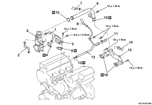
Removal steps


1.
Cooling water line hose


2.
Cooling water line hose


3.
Cooling water outlet hose fitting and thermostat case assembly


4.
Thermostat case gasket


5.
Water pump by-pass inlet fitting


6.
Water pump by-pass inlet fitting gasket


7.
Water hose connection


8.
Water hose connection


9.
Cooling water outlet pipe

>>A<<
10.
O-ring


11.
Heater piping hose connection


12.
Water pump inlet pipe

>>A<<
13.
O-ring


14.
Heater piping hose connection


15.
Cylinder head water by-pass pipe


16.
Cylinder head water by-pass pipe gasket

INSTALLATION SERVICE POINT


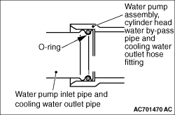
>>A<< O-RING INSTALLATION


caution
  • Care must be taken not to permit engine oil or other greases to adhere to the O-ring.
  • When inserting the pipe, check to be sure that there is no sand, dirt, etc. on its inner surface.

Fit the O-ring to the groove in the water pump inlet pipe and cooling water outlet pipe. Then lubricate the O-ring and the inside of the water pump assembly, cylinder head water by-pass pipe and cooling water outlet hose fitting with water. Then insert the water pump inlet pipe and cooling water outlet pipe to the water pump assembly, cylinder head water by-pass pipe and cooling water outlet hose fitting with water.