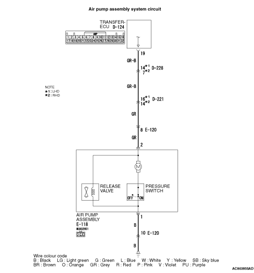
Code No.C1465, C1466: Rear Differential Lock Air Pump Assembly System


OPERATION
DIAGNOSIS CODE SET CONDITIONS
- If the terminal voltage is more than 4 V when the rear differential lock
air pump assembly is not driven, or the terminal voltage is less than 6 V when the rear differential
lock air pump assembly is driven, code No.C1465 is set.
- If the current value is more than 3 A when the rear differential lock air pump assembly
is driven, code No.C1466 is set.
PROBABLE CAUSES
- Malfunction of the rear differential lock air pump assembly
- Damaged harness wires and connectors
- Malfunction of the transfer-ECU
DIAGNOSIS PROCEDURE |
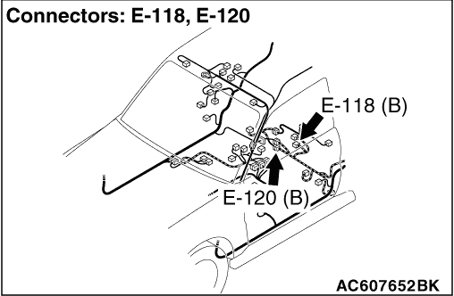
STEP 1. Measure the voltage at rear differential lock air pump assembly connector E-118. |
| (1)Disconnect the connector, and measure the voltage between terminal No.2 and earth
at the wiring harness side. |
| (2)Turn the ignition switch to the ON position. OK: 1 V or less |
Q.
Is the check result normal?
|
 Go to Step 4. Go to Step 4. |
|
 Go to Step 2. Go to Step 2. |
|
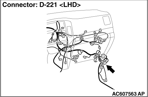
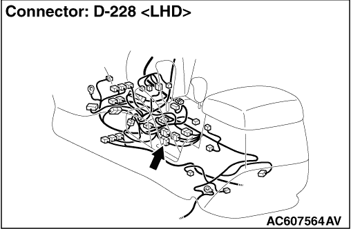
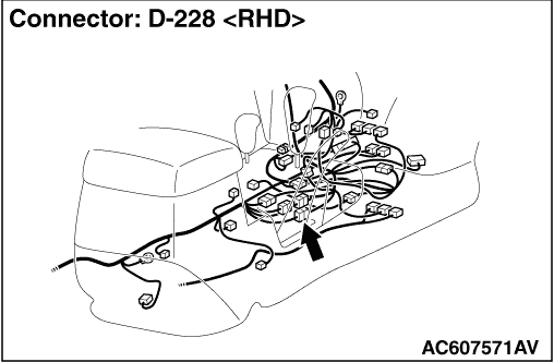
STEP 2. Connector check: E-118 rear differential lock air pump assembly connector, D-221, D-228, E-120 intermediate connector, D-124 transfer-ECU connector. |
| Check for the contact with terminals. |
Q.
Is the check result normal?
|
| Go to Step 3. |
|
| Repair the defective connector. |
|
STEP 3. Check the harness between rear differential lock air pump assembly connector E-118 terminal No.2 and transfer-ECU connector D-124 terminal No.19. |
| Check the power supply line for short (for short to the power supply) circuit. |
Q.
Is the check result normal?
|
| Go to Step 8. |
|
| Repair the wiring harness. |
|
STEP 4. Connector check: E-118 rear differential lock air pump assembly connector, D-221, D-228, E-120 intermediate connector, D-124 transfer-ECU connector. |
| Check for the contact with terminals. |
Q.
Is the check result normal?
|
| Go to Step 5. |
|
| Repair the defective connector. |
|
STEP 5. Check the harness between rear differential lock air pump assembly connector E-118 terminal No.2 and transfer-ECU connector D-124 terminal No.19. |
| Check the power supply line for short (for short to the earth) circuit. |
Q.
Is the check result normal?
|
| Go to Step 6. |
|
| Repair the wiring harness. |
|
STEP 6. Rear differential lock air pump assembly insulation check |
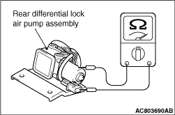 |
Check that no continuity exists between the rear differential lock air pump assembly (case)
and each terminal of the E-118 connector (pump side). OK: 1 MΩ or more Q.
Is the check result normal?Go to Step 7.Replace the rear differential lock air pump assembly (Refer to GROUP 27 - Rear
Differential Lock  ). ). |
STEP 7. Check the rear differential lock air pump assembly. |
| Refer to GROUP 27 - Rear Differential Lock . |
Q.
Is the check result normal?
|
| Go to Step 8. |
|
| Repair the defective connector. |
|
STEP 8. M.U.T.-III data list. |
| Item 29: Air pump motor voltage (Refer to .) |
Q.
Is the check result normal?
|
| Intermittent malfunction (Refer to GROUP 00 - How to Cope with Intermittent
Malfunction ). |
|
| Replace the transfer-ECU. |
|