REMOVAL AND INSTALLATION <4WD>


Pre-removal Operation
  • Fuel Line Pressure Reduction (Refer to GROUP 13A - On-vehicle Service, Reduce Pressurized Fuel Lines ).
  • Draining Fuel
  • Propeller Shaft Removal (Refer to GROUP 25 - Propeller Shaft ).
  • Exhaust Centre Pipe Removal (Refer to GROUP 15 - Exhaust Pipe and Main Muffler ).
  • Rear Seat Cushion Assembly Removal (Refer to GROUP 52A - Rear Seat Assembly ).

Post-installation Operation
  • Rear Seat Cushion Assembly Installation (Refer to GROUP 52A - Rear Seat Assembly ).
  • Exhaust Centre Pipe Installation (Refer to GROUP 15 - Exhaust Pipe and Main Muffler ).
  • Propeller Shaft Installation (Refer to GROUP 25 - Propeller Shaft ).
  • Refilling Fuel
  • Checking for Fuel Leaks (Refer to ).


Removal steps
<<A>>

1.
Fuel tank pump and gauge assembly connector
<<A>>
>>E<<
2.
Fuel main pipe connection
<<B>>

3.
Fuel tank gauge unit connector


4.
Fuel vapour hose and fuel vapour pipe connection


5.
Fuel filler neck breather hose (Fuel filler neck side) connection

>>D<<
6.
Fuel filler hose (Fuel filler neck side) connection


7.
Parking brake rear cable clamp connection


·
Rear suspension crossmember stay (Refer to GROUP 34 - Rear Suspension Crossmember ).


·
Electronic control coupling harness cover (Refer to GROUP 27C - Electronic control 4WD )
<<C>>

·
Electronic control coupling harness connector and harness clamp connection
<<C>>

·
Differential mount bracket mounting bolt
<<C>>

8.
Fuel tank band
<<C>>

9.
Fuel tank assembly


10.
Fuel filler neck breather hose

>>C<<
11.
Fuel filler hose


12.
Fuel shut-off valve


13.
Fuel vapour hose


Removal steps
<<D>>
>>B<<
14.
Fuel tank gauge unit


15.
Fuel tank gauge unit gasket


16.
Fuel pump bracket plate


17.
Suction hose connection
<<D>>
>>A<<
18.
Fuel tank pump and gauge assembly


19.
Fuel tank pump and gauge assembly gasket


20.
Clip


21.
Fuel tank lower protector


22.
Fuel tank

REMOVAL SERVICE POINTS


For service points other than below, follow the same service procedures as 10 MY OUTLANDER.

<<C>> ELECTRONIC CONTROL COUPLING HARNESS CONNECTOR AND HARNESS CLAMP/DIFFERENTIAL MOUNT BRACKET MOUNTING BOLT/FUEL TANK BAND/FUEL TANK ASSEMBLY REMOVAL


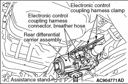
1.Disconnect the electronic control coupling connector, the wiring harness clamp and the breather hose at the rear differential carrier.(Refer to GROUP 27C - Electronic control 4WD )
2.Remove the differential mount bracket bolts, and tilt the differential carrier to hold it on a support stand.(Refer to GROUP 27B - Rear axle )

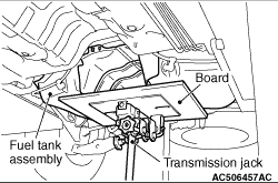
3.Support the fuel tank assembly on a transmission jack, and then remove the fuel tank band securing bolts and the fuel tank assembly connecting nuts.
4.Remove the fuel tank assembly while holding its tilted position and taking care not to strike it with the differential carrier.

INSTALLATION SERVICE POINTS


For service points other than below, follow the same service procedures as 10 MY OUTLANDER.

>>C<< FUEL FILLER HOSE CONNECTION


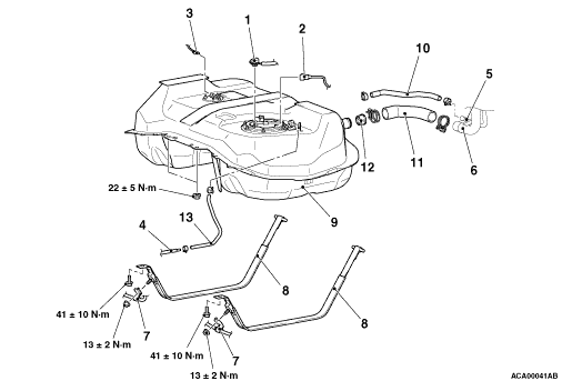
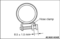
After connecting the fuel filler hose, tighten the bolts of hose clamp so that the tightening dimension is 8.5 ± 1.5 mm.

>>D<< FUEL FILLER HOSE (FUEL FILLER NECK SIDE) CONNECTION


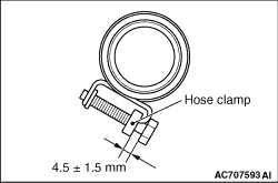
After connecting the fuel filler hose (fuel filler neck side), tighten the bolts of hose clamp so that the tightening dimension is 4.5 ± 1.5 mm.