REMOVAL AND INSTALLATION


caution The part indicated by the * mark should be temporarily tightened, and then fully tightened with the engine and transmission assembly weight applied on the vehicle body.
Pre-removal and post-installation operation
  • Engine Room Under Cover Front A, B and Engine Room Side Cover Removal (Refer to GROUP 51 - Under Cover ).
  • CVT Fluid Draining and Refilling (Refer to .)
  • Engine Coolant Draining and Refilling (Refer to GROUP 14 - On-vehicle Service, Engine Coolant Replacement .)
  • Air Cleaner Assembly, Air Cleaner Bracket Removal and Installation (Refer to GROUP 15 - Air Cleaner .)
  • Battery and Battery Tray Removal and Installation (Refer to GROUP 54A, Battery .)
  • Engine Upper Cover Removal and Installation (Refer to GROUP 11A - Camshaft .)
  • Drive Shaft Removal and Installation (Refer to GROUP 26 - Drive Shaft Assembly .)
  • Centre Member Removal and Installation (Refer to GROUP 32 - Centremember .)
  • Transfer Assembly Removal and Installation <4WD> (Refer to .)
  • Rear Roll Stopper Removal and Installation <4WD> (Refer to GROUP 32 - Engine Roll Stopper and Centre Member .)
  • Transmission Mounting Insulator Removal and Installation (Refer to GROUP 32 - Transmission Mounting .)


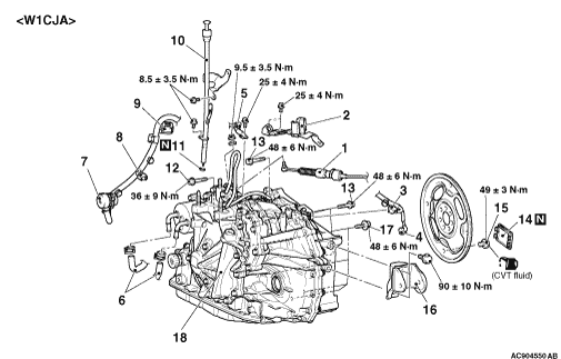
Removal steps

>>C<<
1.
Transmission control cable connection


2.
Transmission control cable bracket


3.
Secondary pulley speed sensor connector


4.
Crank angle sensor connector


5.
Battery earth


6.
Water hose connection
<<A>>

7.
CVT assembly connector connection


8.
Primary pulley rotation sensor connector


9.
Inhibitor switch connector


·
Water tube assembly (Refer to )


·
CVT fluid cooler hose assembly connection (Refer to )


10.
Oil filler tube assembly


11.
O-ring


12.
Starter mounting bolt
<<B>>

13.
Transmission assembly upper part coupling bolt


14.
Cover
<<C>>

15.
Torque converter and drive plate coupling bolt


16.
Rear rolling stopper connection
<<D>>
>>B<<
·
Injector protector mounting bolt


·
Vacuum pipe assembly (Refer to GROUP 14 - Water Hose and Water Pipe .)
<<E>>

·
Engine assembly holding


17.
Transmission assembly lower part coupling bolt

>>A<<
18.
Transmission assembly

REMOVAL SERVICE POINTS


The service procedure is the same as that for 10 MY OUTLANDER excluding the followings.

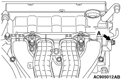
<<D>> INJECTOR PROTECTOR MOUNTING BOLT REMOVAL


Remove the injector protector mounting bolt (A shown in the illustration).

<<E>> ENGINE ASSEMBLY HOLDING


1.
caution Since A and B in the figure differ in height, adjust the height by using the washer (approximately 1.5 mm) at B before tightening the bolts to the specified torque.
Tighten the engine hanger plate (special tool: MB992201) to the specified torque at A in the figure (injector protector mounting bolt) and B in the figure (vacuum pipe assembly mounting bolt).
Tightening torque: 20 ± 2 N·m (A in the figure)
Tightening torque: 11 ± 1 N·m (B in the figure)

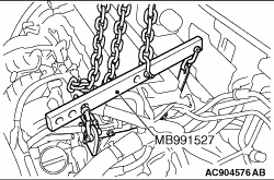
2.Install the engine hanger (special tool: MB991527).


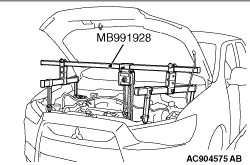
3.<When engine hanger (special tool: MB991928) is used>
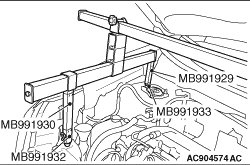
(1) Assemble the engine hanger (special tool: MB991928). (Set the components below to the base hanger.)

  • Slide bracket (HI)
  • Foot x 2 (standard) (MB991932)
  • Foot x 2 (short) (MB991933)
  • Joint x 2 (50) (MB991929)
  • Joint x 2 (90) (MB991930)
(2) Set the foot of the special tool as shown in the figure.
note Adjust the engine hanger balance by sliding the slide bracket (HI).
(3) Set the chain to the engine hanger (special tool: MB991527) to support the engine and transmission assembly. Remove the garage jack, and then remove the transmission assembly upper part coupling bolts that have been loosened previously.


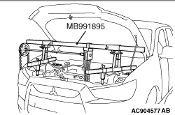
4.<When engine hanger (special tool: MB991895) is used>
(1) Set the foot of engine hanger (Special tool: MB991895) as shown in the figure.
note Slide the front foot of engine hanger (special tool: MB991895) to balance the engine hanger.
(2) Set the chain to the engine hanger (special tool: MB991527) to support the engine and transmission assembly. Remove the garage jack, and then remove the transmission assembly upper part coupling bolts that have been loosened previously.

INSTALLATION SERVICE POINT


The service procedure is the same as that for 10 MY OUTLANDER excluding the followings.

>>B<< INJECTOR PROTECTOR MOUNTING BOLT INSTALLATION


Tighten the injector protector mounting bolt (A in the figure) to the specified torque.
Tightening torque: 20 ± 2 N·m