REMOVAL AND INSTALLATION


Pre-removal Operation
  • Engine Room Under Cover Front A, B and Engine Room Side Cover Removal (Refer to GROUP 51 - Under Cover ).
  • Engine Cover Removal
  • Cowl Top Panel Removal (Refer to GROUP 42A - Loose Panel ).
  • Front Exhaust Pipe Removal (Refer to GROUP 15 - Exhaust Pipe and Main Muffler <BWC> ).
  • Intercooler Air Pipe D, Intercooler Air Pipe Bracket and Pressure Hose Assembly Removal (Refer to GROUP 15 - Intercooler ).
  • Rear Roll Stopper and Transmission Case Rear Roll Stopper Bracket Removal (Refer to GROUP 22A - Transmission Assembly ).

Post-installation Operation
  • Rear Roll Stopper and Transmission Case Rear Roll Stopper Bracket Installation (Refer to GROUP 22A - Transmission Assembly ).
  • Intercooler Air Pipe D, Intercooler Air Pipe Bracket and Pressure Hose Assembly Installation (Refer to GROUP 15 - Intercooler ).
  • Front Exhaust Pipe Installation (Refer to GROUP 15 - Exhaust Pipe and Main Muffler <BWC> ).
  • Cowl Top Panel Installation (Refer to GROUP 42A - Loose Panel ).
  • Engine Cover Installation
  • Engine Room Under Cover Front A, B and Engine Room Side Cover Installation (Refer to GROUP 51 - Under Cover ).


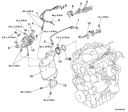
Removal steps


1.
Air/fuel ratio sensor connector connection
<<A>>
>>B<<
2.
Air/fuel ratio sensor


3.
Exhaust gas temperature sensor connectors connection


4.
Variable geometry position sensor connector connection


5.
No.3 exhaust gas temperature sensor
<<B>>
>>A<<
6.
No.1 exhaust gas temperature sensor


7.
No.2 exhaust gas temperature sensor


8.
EGR cooler solenoid valve connector connection


9.
Exhaust differential pressure sensor connector connection


10.
Exhaust gas temperature sensor bracket


11.
Vacuum hose connection


12.
Pressure pipe bracket


13.
Exhaust differential pressure sensor assembly


14.
Clamp


15.
DPF bracket


16.
DPF assembly


17.
Seal ring

REMOVAL SERVICE POINTS


<<A>> AIR/FUEL RATIO SENSOR REMOVAL


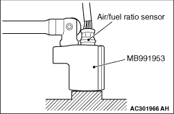
Remove the connection and clamp of air/fuel ratio sensor connector, and then use special tool oxygen sensor wrench (MB991953) to remove the air/fuel ratio sensor.

<<B>> NO.1 EXHAUST GAS TEMPERATURE SENSOR REMOVAL


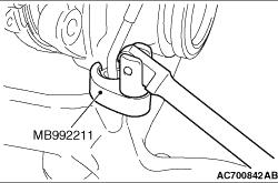
Remove the connection and clamp of No.1 exhaust gas temperature sensor connector, and then use special tool crowfoot wrench (MB992211) to remove the No.1 exhaust gas temperature sensor.

INSTALLATION SERVICE POINTS


>>A<< NO.1 EXHAUST GAS TEMPERATURE SENSOR INSTALLATION


Tighten the No.1 exhaust gas temperature sensor to the specified torque by using special tool crowfoot wrench (MB992211).
Tightening torque: 46 ± 6 N·m

>>B<< AIR/FUEL RATIO SENSOR INSTALLATION


Tighten the air/fuel ratio sensor to the specified torque by using special tool oxygen sensor wrench (MB991953).
Tightening torque: 50 ± 10 N·m