REMOVAL AND INSTALLATION <F6MBA>


caution
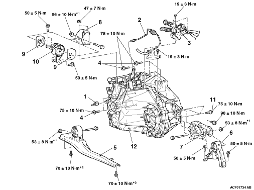
  • The part indicated by the *1 mark should be temporarily tightened, and then fully tightened with the engine and transmission assembly weight applied on the vehicle body.
  • The bolts marked with *2 are coated with the friction coefficient stabilizer. After removing these bolts, make sure that they are free of damage, remove any dust and dirt on the bearing surfaces and the threads, and then securely tighten to the specified torque.
Pre-removal operation
  • Engine Room Under Cover and Engine Room Side Cover Removal (Refer to GROUP 51, Under Cover ).
  • Transmission Oil Draining (Refer to ).
  • Air Cleaner Assembly and Air Cleaner Bracket Removal (Refer to GROUP 15, Air Cleaner ).
  • Battery and Battery Tray Removal (Refer to GROUP 54A, Battery ).
  • Headlamp Support Panel Cover Removal (Refer to GROUP 51, Front Bumper Assembly and Radiator Grille ).
  • Engine-ECU Removal (Refer to GROUP 13D, Engine-ECU ).
  • Engine Cover Removal (Refer to GROUP 11G, Engine Assembly ).
  • Cowl Top Panel Removal (Refer to GROUP 42A, Loose Panel ).
  • Starter Motor Assembly Removal (Refer to GROUP 16, Stator Motor Assembly ).
  • Drive Shaft Removal (Refer to GROUP 26, Drive Shaft Assembly ).
  • Front Exhaust Pipe Removal (Refer to GROUP 15, Exhaust Pipe and Main Muffler ).

Post-installation operation
  • Front Exhaust Pipe Installation (Refer to GROUP 15, Exhaust Pipe and Main Muffler ).
  • Drive Shaft Installation (Refer to GROUP 26, Drive Shaft Assembly ).
  • Starter Motor Assembly Installation (Refer to GROUP 16, Stator Motor Assembly ).
  • Cowl Top Panel Installation (Refer to GROUP 42A, Loose Panel ).
  • Engine Cover Installation (Refer to GROUP 11G, Engine Assembly ).
  • Engine-ECU Installation (Refer to GROUP 13D, Engine-ECU ).
  • Headlamp Support Panel Cover Installation (Refer to GROUP 51, Front Bumper Assembly and Radiator Grille ).
  • Clutch Bleeding and Clutch Fluid Refilling (Refer to ).
  • Battery and Battery Installation (Refer to GROUP 54A, Battery ).
  • Air Cleaner Assembly and Air Cleaner Bracket Installation (Refer to GROUP 15, Air Cleaner ).
  • Transmission Oil Refilling (Refer to ).
  • Engine Room Under Cover and Engine Room Side Cover Installation (Refer to GROUP 51, Under Cover ).


Removal steps


1.
Back-up lamp switch connector connection
<<A>>
>>C<<
2.
Clutch tube connection
<<B>>

3.
Cable bracket and transmission control cable assembly <Transmission side>
<<C>>

4.
Transmission assembly upper part coupling bolts


5.
Centre member assembly


6.
Rear roll stopper


7.
Transmission case rear roll stopper bracket
<<D>>

8.
Transmission mounting bracket

>>B<<
9.
Transmission mounting insulator stopper


10.
Transmission mounting insulator
<<E>>

·
Engine assembly supporting


11.
Transmission assembly lower part coupling bolts

>>A<<
12.
Transmission assembly

REMOVAL SERVICE POINTS


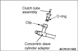
<<A>> CLUTCH TUBE CONNECTION


caution
  • Do not remove the O-ring and the clip from the clutch tube and the concentric slave cylinder adapter.
  • If the O-ring or the clip of the clutch tube and the concentric slave cylinder adapter are damaged, replace each assembly.

<<B>> CABLE BRACKET AND TRANSMISSION CONTROL CABLE ASSEMBLY REMOVAL <TRANSMISSION SIDE>


caution Be careful not to pull out the cable directly to disconnect the joint because the cable could be broken.
Use the clip remover (special tool: MB992277), and disconnect the joint.

<<C>> TRANSMISSION ASSEMBLY UPPER PART COUPLING BOLTS REMOVAL


Only loosen the each bolt from the engine and transmission assembly (do not remove).

<<D>> TRANSMISSION MOUNTING BRACKET REMOVAL


1.Place a garage jack against the transmission case with a piece of wood in between to support the engine and transmission assembly.
2.Operate a garage jack so that the weight of the engine and transmission assembly is not applied to the transmission mounting insulator, and remove the transmission mounting bracket.

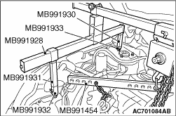
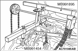
<<E>> ENGINE ASSEMBLY SUPPORTING


1.Set the engine hanger balancer (special tool: MB991454) to the engine hanger bracket.


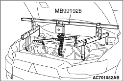
2.<When engine hanger (Special tool: MB991928) is used>
(1) Assemble the engine hanger (Special tool: MB991928). (Set the components below to the base hanger.)

  • Slide bracket (HI)
  • Foot (standard) x 2 (MB991932)
  • Foot (short) x 2 (MB991933)
  • Joint (90) x 2 (MB991930)
  • Joint (140) x 2 (MB991931)
(2) Set the feet of the special tool as shown in the figure.
note Adjust the engine hanger balance by sliding the slide bracket (HI).
(3) Hook the chains on the engine hanger plate (special tool: MB992201) to support the engine and transmission assembly. Remove the garage jack and then remove the transmission assembly upper fixing bolts.


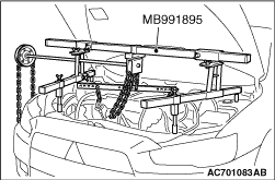
3.<When using engine hanger (Special tool: MB991895)>
(1) Set the foot of the engine hanger (Special tool: MB991895) as shown in the figure.
note Slide the front foot of the engine hanger (Special tool: MB991895) to balance the engine hanger.
(2) Hook the chains on the engine hanger plate (special tool: MB992201) to support the engine and transmission assembly. Remove the garage jack and then remove the transmission assembly upper fixing bolts.

INSTALLATION SERVICE POINTS


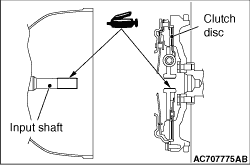
>>A<< TRANSMISSION ASSEMBLY INSTALLATION


When installing the transmission assembly, apply the specified grease to the spline of clutch disc and input shaft.
Specified grease: Mitsubishi Part No.0101011 or equivalent

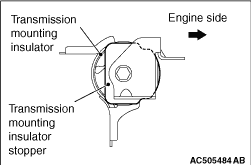
>>B<< TRANSMISSION MOUNTING INSULATOR STOPPER INSTALLATION


Install the transmission mounting insulator stopper as shown in the figure.

>>C<< CLUTCH TUBE INSTALLATION


caution
  • Check that the O-ring and the clip are not damaged before installing the clutch tube and the concentric slave cylinder adapter.
  • If the O-ring of the clutch tube and the concentric slave cylinder adapter and their installation positions are contaminated, clean with the clutch fluid before installation.
After installing the clip to the concentric slave cylinder adapter, install the clutch tube assembly to the concentric slave cylinder adapter.