CLUTCH PEDAL AND MASTER CYLINDER REMOVAL AND INSTALLATION


caution Do not apply grease or lubricant to the switch and the switch installation section to avoid malfunction of the switch. In addition, do not use gloves which have grease on them.

Pre-removal Operation
  • Air Cleaner Assembly Removal (Refer to GROUP 15 - Air Cleaner <4A9>, <4B1>, <BWC>). <LHD>
  • Battery and Battery Tray Removal (Refer to GROUP 54A - Battery ). <LHD>
  • ETACS-ECU Removal (Refer to GROUP 54A - ETACS-ECU ). <LHD>
  • Bottom Cover Assembly (driver’s side) Removal (Refer to GROUP 52A - Instrument Panel Assembly ). <RHD>

Post-installation Operation
  • Bottom Cover Assembly (driver’s side) Installation (Refer to GROUP 52A - Instrument Panel Assembly ). <RHD>
  • ETACS-ECU Installation (Refer to GROUP 54A - ETACS-ECU ). <LHD>
  • Battery and Battery Tray Installation (Refer to GROUP 54A - Battery ). <LHD>
  • Air Cleaner Assembly Installation (Refer to GROUP 15 - Air Cleaner <4A9>, <4B1>, <BWC>). <LHD>
  • Clutch Fluid Supplying
  • Clutch Bleeding (Refer to ).
  • Clutch Pedal Check (Refer to ).


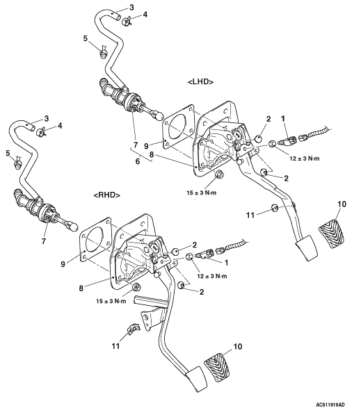
Removal steps

>>B<<
1.
Clutch switch <vehicles with auto-cruise control system>


2.
Stopper


3.
Reservoir hose and brake fluid reservoir connection


4.
Hose clip
<<A>>
>>A<<
5.
Clutch tube assembly A connection
<<B>>

6.
Clutch master cylinder and clutch pedal assembly <LHD>
<<C>>

7.
Clutch master cylinder


8.
Clutch pedal assembly


9.
Sealer


10.
Pedal pad


11.
Stopper

REMOVAL SERVICE POINT


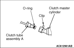
<<A>> CLUTCH TUBE ASSEMBLY A CONNECTION REMOVAL


caution
  • Do not remove the O-rings and the clips from the clutch tube assembly A and the clutch master cylinder.
  • If the O-rings or the clips of the clutch tube assembly A and the clutch master cylinder are damaged, replace each assembly.

<<B>> CLUTCH MASTER CYLINDER AND CLUTCH PEDAL ASSEMBLY REMOVAL <LHD>


Remove the clutch master cylinder and clutch pedal assembly from inside the vehicle.

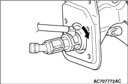
<<C>> CLUTCH MASTER CYLINDER REMOVAL


Pull out the clutch master cylinder by turning the cylinder 45° to the direction of the arrow shown in the figure.

INSTALLATION SERVICE POINT


>>A<< CLUTCH TUBE ASSEMBLY A CONNECTION INSTALLATION


caution
  • Check that the O-rings and the clips are not damaged before installing the clutch tube assembly A and the clutch master cylinder.
  • If the O-rings of the clutch tube assembly A and the clutch master cylinder and their installation positions are contaminated, clean with the clutch fluid before installation.
After installing the clip to the clutch master cylinder, install the clutch tube assembly A to the clutch master cylinder.

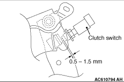
>>B<< CLUTCH SWITCH INSTALLATION


Install the clutch switch at the specified dimension when the clutch pedal is released.