Pre-removal operation
- Engine Room Under Cover and Engine Room Side Cover Removal (Refer to GROUP 51, Under Cover
 ). ).
- Transmission Oil Draining (Refer to ).
- Air Cleaner Assembly and Air Cleaner Bracket Removal (Refer to GROUP 15, Air Cleaner ).
- Battery and Battery Tray Removal (Refer to GROUP 54A, Battery ).
- Headlamp Support Panel Cover Removal (Refer to GROUP 51, Front Bumper Assembly and Radiator Grille ).
- Engine-ECU Removal (Refer to GROUP 13A, Engine-ECU ).
- Engine Cover Removal (Refer to GROUP 11A, Engine Assembly ).
- Starter Motor Assembly Removal (Refer to GROUP 16, Stator Motor Assembly ).
- Drive Shaft Removal (Refer to GROUP 26, Drive Shaft Assembly ).
|
Post-installation operation
- Drive Shaft Installation (Refer to GROUP 26, Drive Shaft Assembly ).
- Starter Motor Assembly Installation (Refer to GROUP 16, Stator Motor Assembly ).
- Engine Cover Installation (Refer to GROUP 11A, Engine Assembly ).
- Engine-ECU Installation (Refer to GROUP 13A, Engine-ECU ).
- Headlamp Support Panel Cover Installation (Refer to GROUP 51, Front Bumper Assembly and Radiator Grille ).
- Clutch Bleeding and Clutch Fluid Refilling (Refer to ).
- Battery and Battery Installation (Refer to GROUP 54A, Battery ).
- Air Cleaner Assembly and Air Cleaner Bracket Installation (Refer to GROUP 15, Air Cleaner ).
- Transmission Oil Refilling (Refer to ).
- Engine Room Under Cover and Engine Room Side Cover Installation (Refer to GROUP 51, Under Cover ).
|

|
| caution |
Be careful not to pull out the cable directly to disconnect the joint because the cable could be broken.
|
Use the clip remover (special tool: MB992277), and disconnect the joint.
|
|
|
Only loosen the each bolt from the engine and transmission assembly (do not remove).
|
|
|
1.Place a garage jack against the transmission case with a piece of wood in between to support the engine and transmission assembly.
|
|
|
2.Operate a garage jack so that the weight of the engine and transmission assembly is not applied to the transmission mounting insulator, and remove the transmission mounting bracket.
|
|
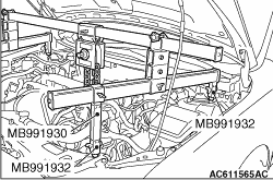
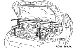
1.<When engine hanger (Special tool: MB991928) is used>
(1)
Assemble the engine hanger (Special tool: MB991928). (Set the components below to the base hanger.)
- Slide bracket (HI)
- Foot x 4 (standard) (MB991932)
- Joint x 2 (90) (MB991930)
(2)
Set the feet of the special tool as shown in the figure.
|
|
| note |
Adjust the engine hanger balance by sliding the slide bracket (HI).
|
|
(3)
Set the engine hanger (Special tool: MB991928) to support the engine and transmission assembly
Remove the garage jack and then remove the transmission assembly upper part coupling bolts that have been loosened previously.
|
|
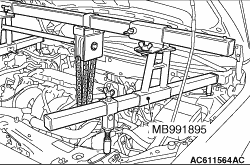
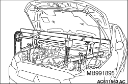
2.<When using engine hanger (Special tool: MB991895)>
(1)
Set the foot of the engine hanger (Special tool: MB991895) as shown in the figure.
|
|
| note |
Slide the front foot of the engine mechanical hanger (Special tool: MB991895) to balance the engine hanger.
|
|
(2)
Set the engine hanger (Special tool: MB991895) to support the engine and transmission assembly.
Remove the garage jack and then remove the transmission assembly upper part coupling bolts that have been loosened previously.
|
|
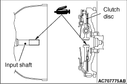
When installing the transmission assembly, apply the specified grease to the spline of clutch disc and input shaft.
Specified grease: Molywhite TA No.2
|
|
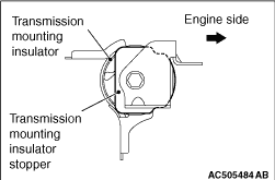
Install the transmission mounting insulator stopper as shown in the figure.
|
