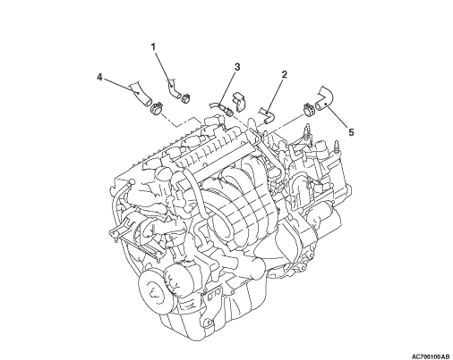
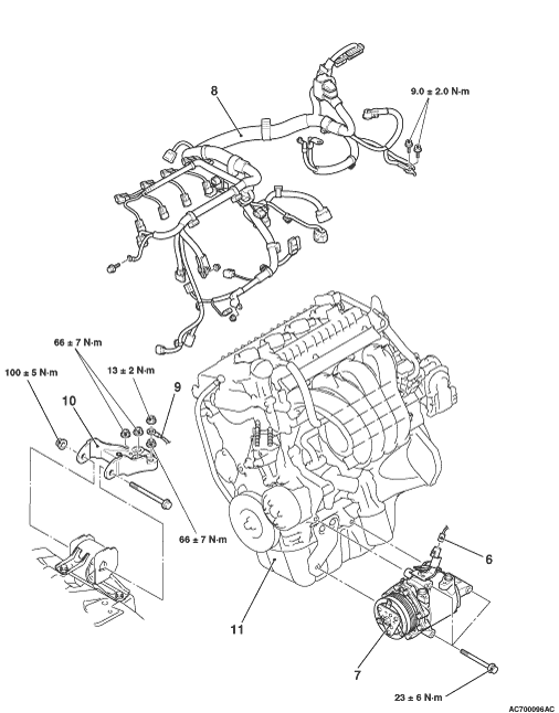
Pre-removal operation
- Hood Removal (Refer to GROUP 42A - Hood
 ). ).
- Fuel Line Pressure Reduction [Refer to GROUP 13A - On-vehicle Service, Fuel Pump Connector Disconnection (How to Reduce Pressurized Fuel Lines) ].
- Engine Room Under Cover Front A, B and Engine Room Side Cover Removal (Refer to GROUP 51 - Under Cover ).
- Engine Coolant Draining (Refer to GROUP 14 - On-vehicle Service, Engine Coolant Replacement ).
- Engine Oil Draining (Refer to GROUP 12 - On-vehicle Service, Engine Oil Replacement ).
- Transmission Oil Draining (Refer to GROUP 22A - On-vehicle Service, Transmission Oil Change ) <M/T>.
- Automatic Transmission Oil Draining (Refer to GROUP 23C - On-vehicle Service, Automatic Transmission Fluid Change ) <A/T>.
- Engine Upper Cover Removal (Refer to ).
- Air Cleaner Intake Hose and Air Cleaner Assembly Removal (Refer to GROUP 15 - Air Cleaner ).
- Battery and Battery Tray Removal (Refer to GROUP 54A - Battery ).
- Engine-ECU Removal (Refer to GROUP 13A - Engine-ECU ).
- Radiator Removal (Refer to GROUP 14 - Radiator ).
- Alternator and Others Belt Removal (Refer to ).
- Alternator and Alternator Brace Removal (Refer to GROUP 16 - Charging System, Alternator Assembly ).
|
Post-installation operation
- Alternator and Alternator Brace Installation (Refer to GROUP 16 - Charging System, Alternator Assembly ).
- Alternator and Others Belt Installation (Refer to ).
- Radiator Installation (Refer to GROUP 14 - Radiator ).
- Engine-ECU Installation (Refer to GROUP 13A - Engine-ECU ).
- Battery and Battery Tray Installation (Refer to GROUP 54A - Battery ).
- Air Cleaner Intake Hose and Air Cleaner Assembly Installation (Refer to GROUP 15 - Air Cleaner ).
- Transmission Oil Refilling (Refer to GROUP 22A - On-vehicle Service, Transmission Oil Change ) <M/T>.
- Automatic Transmission Oil Refilling (Refer to GROUP 23C - On-vehicle Service, Automatic Transmission Fluid Change ) <A/T>.
- Engine Oil Refilling (Refer to GROUP 12 - On-vehicle Service, Engine Oil Replacement ).
- Engine Coolant Refilling (Refer to GROUP 14 - On-vehicle Service, Engine Coolant Replacement ).
- Alternator and Others Belt Tension Check (Refer to ).
- Engine Upper Cover Installation (Refer to ).
- Engine Room Under Cover Front A, B and Engine Room Side Cover Installation (Refer to GROUP 51 - Under Cover ).
- Fuel Leak Check
- Hood Installation (Refer to GROUP 42A - Hood ).
|

|
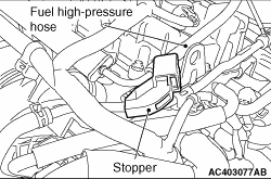
2.Raise the retainer, and pull out the fuel high-pressure hose.
| note |
If the retainer comes off, install it securely after pulling out the fuel high-pressure hose.
|
|
|
|
1.With the hose installed, remove the A/C compressor and clutch assembly from the cylinder block.
|
|
|
2.Secure the removed A/C compressor and clutch assembly with cord or rope at a position where they will not interfere with the removal of the engine assembly.
|
|
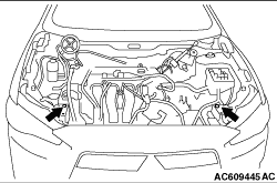
1.Install the headlamp support panel upper bolt to the position as shown in the figure.
2.Remove the transmission assembly. (Refer to GROUP 22A - Transmission Assembly ) <M/T>, (Refer to GROUP 23C - Transmission Assembly ) <A/T>.
|
|
|
1.
| caution |
When supporting the engine assembly with a garage jack, be careful not to deform the engine oil pan.
|
Place a garage jack against the engine oil pan with a piece of wood in between to support the engine assembly.
|


|
2.Remove special tools engine hanger (MB991928 or MB991895) and engine hanger plate (MB992201) which was installed for supporting the engine assembly when the transmission assembly was removed.
3.Operate a garage jack so that the engine weight is not applied to the engine mounting insulator, and remove the engine mounting insulator.
|

|
1.Install the chain of special tool engine hanger balancer (MB991454) and special tool engine hanger (MB991527), and set the chain block.
2.After checking that all cables, hoses and wiring harness connectors and so on are disconnected from the engine, lift the engine assembly slowly with the chain block to remove the engine assembly upward from the engine compartment.
|
|
Install the engine assembly, being careful not to pinch the cables, hoses, or wiring harness connectors.
|
|
|
1.
| caution |
When supporting the engine assembly with a garage jack, be careful not to deform the engine oil pan.
|
Place a garage jack against the engine oil pan with a piece of wood in between, and install the engine mounting insulator while adjusting the position of the engine.
|
|
2.Install special tool engine hanger (MB991928 or MB991895) which is used during installation of transmission assembly to hold the engine assembly (Refer to GROUP 22A - Transmission Assembly ) <M/T>, (Refer to GROUP 23C - Transmission Assembly ) <A/T>.
|
|
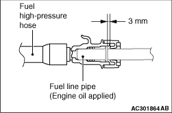
Apply a small amount of engine oil to the fuel line pipe, and install the fuel high-pressure hose.
|