REMOVAL AND INSTALLATION


Pre-removal Operation
  • Floor console bracket (A) and floor console side cover removal (Refer to GROUP 52A - Floor Console Assembly .)
  • Instrument panel cover lower removal <Vehicles with instrument panel cover lower> (Refer to GROUP 52A - Instrument Lower Panel .)
  • Steering column lower cover removal (Refer to GROUP 37A - Steering Shaft .)
  • Foot duct (driver’s side) removal (Refer to GROUP 55A - Duct .)

Post-installation Operation
  • Foot duct (driver’s side) installation (Refer to GROUP 55A - Duct .)
  • Steering column lower cover installation (Refer to GROUP 37A - Steering Shaft .)
  • Instrument panel cover lower installation <Vehicles with instrument panel cover lower> (Refer to GROUP 52A - Instrument Lower Panel .)
  • Floor console bracket (A) and floor console side cover installation (Refer to GROUP 52A - Floor Console Assembly .)
  • Key interlock mechanism check (Refer to .)
  • Shift lock mechanism check (Refer to .)
  • Shift lever operation check (Refer to .)


Removal steps (Cont.)


1.
Band clip


2.
Wiring harness clip

>>B<<
3.
Key interlock cable connection (shift lever side)
<<A>>
>>A<<
4.
Key interlock cable connection (steering side)


5.
Key interlock cable

REMOVAL SERVICE POINT


<<A>> KEY INTERLOCK CABLE (STEERING SIDE) REMOVAL


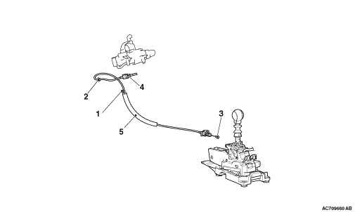
Turn the ignition switch to the ACC position and then pull the key interlock cable out from the ignition key cylinder.

INSTALLATION SERVICE POINTS


>>A<< KEY INTERLOCK CABLE (STEERING SIDE) INSTALLATION


Turn the ignition switch to the ACC position and then install the key interlock cable to the ignition key cylinder.

>>B<< KEY INTERLOCK CABLE (SHIFT LEVER SIDE) INSTALLATION


caution Leave the ignition switch in the LOCK (OFF) position until the key interlock cable installation is completed.
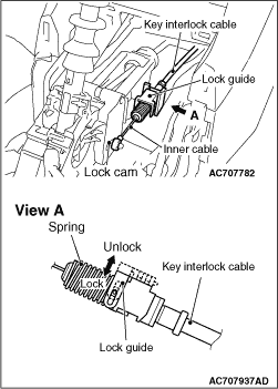
1.Move the shift lever to the P position, and turn the ignition switch to the LOCK (OFF) position.

2.Install the tip of key interlock cable to the lock cam of shift lever assembly, using a caution not to twist the inner cable.
3.Install the adjuster case with its lock guide pulled up (unlocked).
4.Firmly push down the lock guide to lock it.
note The lock position of the key interlock cable is automatically adjusted by a spring.