|
|
Remove the knob cap while pressing the two projections.
|
|
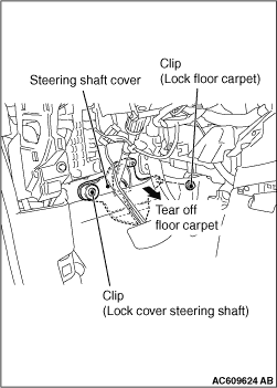
- Remove the clip (for securing the floor carpet), and
turn back the floor carpet.
- Remove the clip (for securing the steering shaft cover), and then remove the steering
shaft cover.
|
|
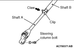
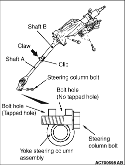
- Remove the steering column bolt connecting the steering gear
to the steering column assembly.
- Disconnect the steering gear from the steering column assembly while sliding the
shaft A to the shaft B with the clip claw as shown in the figure is pinched.
|
|
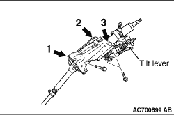
Ensure that the tilt lever is in the lock position, and install the steering column as
below.
- Hand-tighten the mounting bolts in the order of 1,
2, 3, and tighten them in the order of 3, 2, 1, to the specified torque.
- Assemble the steering column assembly to the steering gear.
- Insert the bolt connecting the steering column assembly with the steering gear into
the non-threaded bolt hole.
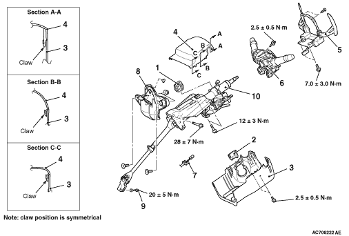
Tightening torque:
- Mounting bolt 1: 28 ± 7 N·m
- Mounting bolt 2, 3: 12 ± 3 N·m
|
|
Ensure that the tilt lever is in the lock position, and install the steering column as
below.
1.While pinching the clip claw part as shown in the figure, slide the shaft A from the
shaft B, and then connect the steering column shaft assembly and steering gear & linkage.
2.Insert the steering column bolt from the no-thread cutting bolt hole and tighten it
to the specified torque.
Tightening torque: 20 ± 5 N·m
|