|
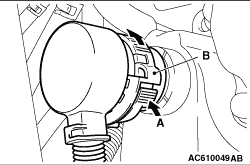
While pressing A in the figure, turn B anti-clockwise to unlock the CVT assembly connector,
and disconnect the connector.
|
|
|
Only loosen the bolts from the engine and transmission assembly (do not remove).
|
|
|
1.Remove the coupling bolts while turning the crankshaft.
|
|
|
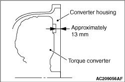
2.Fully push the torque converter into the transmission side so that it does not remain
on the engine side.
|
|
|
1.Place a garage jack against the transmission case with a piece of wood in between
to support the engine and transmission assembly.
|
|
|
2.Operate a garage jack so that the weight of the engine and transmission assembly is
not applied to the transmission mounting insulator, and remove the transmission mounting bracket.
|
|
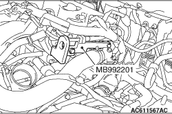
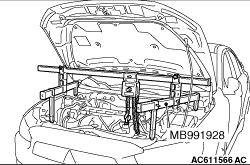
1.Remove the vacuum pipe assembly (Refer to GROUP 14, Water Hose and Water Pipe  ),
and install the engine hanger plate (special tool: MB992201) to the position as shown in the
figure. ),
and install the engine hanger plate (special tool: MB992201) to the position as shown in the
figure.
|
|
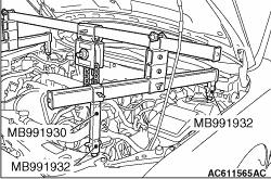
2.<When engine hanger (Special tool: MB991928) is used>
(1)
Assemble the engine hanger (Special tool: MB991928). (Set the components
below to the base hanger.)
- Slide bracket (HI)
- Foot x 4 (standard) (MB991932)
- Joint x 2 (90) (MB991930)
(2)
Set the feet of the special tool as shown in the figure.
|
|
| note |
Adjust the engine hanger balance by sliding the slide bracket (HI).
|
|
(3)
Set the chains of engine hanger plate (special tool: MB992201) to support the engine and
transmission assembly. Remove the garage jack and then remove the transmission assembly upper
part coupling bolts that have been loosened previously.
|
|
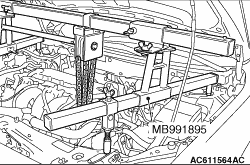
3.<When using engine mechanical hanger (Special tool: MB991895)>
(1)
Set the foot of the engine mechanical hanger (Special tool: MB991895) as shown in the
figure.
|
|
| note |
Slide the front foot of the engine mechanical hanger (Special tool: MB991895) to balance
the engine hanger.
|
|
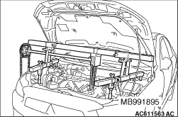
(2)
Set the chains of engine hanger plate (special tool: MB992201) to support the engine and
transmission assembly. Remove the garage jack and then remove the transmission assembly upper
part coupling bolts that have been loosened previously.
|
|
Fully push the torque converter into the transmission side, and then assemble the transmission
assembly to the engine.
|
|
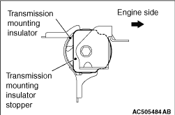
Install the transmission mounting insulator stopper as shown in the figure.
|
|
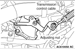
1.Move the selector lever and manual control lever to the N position.
2.Use the adjusting nut to tighten the transmission control cable to the specified torque.
Tightening torque: 9.5 ± 3.5 N·m
|