|
|
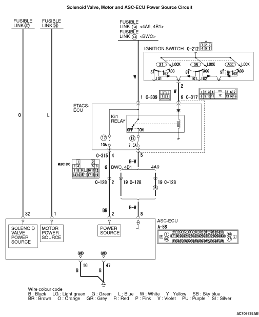
- ASC-ECU contains the power supply circuit (terminal No.32)
for the solenoid valve. The solenoid valve is energised by the valve relay, which is incorporated
in ASC-ECU.
- ASC-ECU contains the power supply circuit (terminal No.2) for ASC-ECU. The power
is supplied from the fusible link No.34 <4A9, 4B1> or fusible link No.44 <BWC> through
the multi-purpose fuse No.17.
- ASC-ECU contains the power supply circuit (terminal No. 8) for ASC-ECU. When the
ignition switch (IG1) is turned ON, the voltage is applied to the relay incorporated in ETACS-ECU
to turn ON the relay, and the power is supplied from the fusible link No. 34 <4A9,
4B1> or fusible link No.44 <BWC> through multi-purpose fuse No. 12.
- When malfunction occurs in ASC-ECU power supply, the communication with M.U.T.-III
becomes unavailable.
|
|
|
- Damaged wiring harness and connectors
- Fuse and fusible link malfunction
- Improper tightening of battery terminal
- Improper tightening of earth bolt
- Battery failure
- Charging system failed
- ASC-ECU malfunction
|
|
|
Refer to GROUP 54A - Battery Test  . .
|
|
|
Q.
Is the battery in good condition?
|
|
|
 Charge or replace the battery. Then go to Step 2. Charge or replace the battery. Then go to Step 2.
|
|
|
|
|
|
Refer to GROUP 16 - Charging System <4A9>, <4B1>, <BWC>, <4B1-T/C>.
|
|
|
Q.
Is the charging system in good condition?
|
|
|
Repair or replace the charging system component(s).
|
|
|
|
|
|
Q.
Is the check result normal?
|
|
|
NO : Repair the damaged connector.
|
|
|
|
|
|
Q.
Is the check result normal?
|
|
|
(1)Removal the fusible link No.27.
|

|
(2)Disconnect the ASC-ECU connector, connect special tool ASC check harness (MB991997) to
the harness-side connector, and then measure the resistance at the special tool connector side.
| note |
Do not connect the special tool ASC check harness (MB991997) to ASC-ECU.
|
(3)Resistance between the terminal No.32 and the body earth.
OK: No continuity
Q.
Is the check result normal?
 Replace the fusible link No.27. Then go to Step 21. Replace the fusible link No.27. Then go to Step 21.
The short circuit may be present in the power supply circuit. Repair the wiring
harness between the A-58 ASC-ECU connector terminal No.32 and the fusible link No.27, and then
replace the fusible link No.27. Then go to Step 21.
|

|
(1)Disconnect the ASC-ECU connector, connect special tool ASC check harness (MB991997) to
the harness-side connector, and then measure the voltage at the special tool connector side.
| note |
Do not connect the special tool ASC check harness (MB991997) to ASC-ECU.
|
(2)Measure the voltage between terminal No.32 and body earth.
OK: Approximately battery voltage
Q.
Is the check result normal?
Go to Step 7.
The open circuit may be present in the power supply circuit. Repair the wiring
harness between the A-58 ASC-ECU connector terminal No.32 and the fusible link No.27. Then go
to Step 21.
|
|
|
Visually check for open circuit in fuse No.12.
|
|
|
Q.
Is the check result normal?
|
|
|
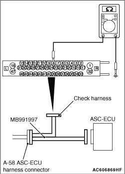
(1)Disconnect the C-317 ETACS-ECU connector.
|
|
(2)Disconnect the ASC-ECU connector, connect special tool ASC check harness (MB991997) to
the harness-side connector, and then measure the resistance at the special tool connector side.
| note |
Do not connect the special tool ASC check harness (MB991997) to ASC-ECU.
|
(3)Resistance between the terminal No.8 and the body earth.
OK: No continuity
Q.
Is the check result normal?
Replace the fuse No.12. Then go to Step 21.
The short circuit may be present in the power supply circuit. Repair the wiring
harness between the A-58 ASC-ECU connector terminal No.8 and the C-317 ETACS-ECU connector terminal
No.5, and then replace the fuse No.12. Then go to Step 21.
|
|
|
Visually check for open circuit in fuse No.17.
|
|
|
Q.
Is the check result normal?
|
|
|
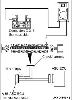
(1)Disconnect the C-315 ETACS-ECU connector.
|

|
(2)Disconnect the ASC-ECU connector, connect special tool ASC check harness (MB991997) to
the harness-side connector, and then measure the resistance at the special tool connector side.
| note |
Do not connect the special tool ASC check harness (MB991997) to ASC-ECU.
|
(3)Resistance between the terminal No.2 and the body earth.
OK: No continuity
Q.
Is the check result normal?
Replace the fuse No.17. Then go to Step 21.
The short circuit may be present in the power supply circuit. Repair the wiring
harness between the A-58 ASC-ECU connector terminal No.2 and the C-315 ETACS-ECU connector terminal
No.4, and then replace the fuse No.17. Then go to Step 21.
|
|
|
(1)Disconnect the connector, and measure at the wiring harness-side connector.
|
|
|
(2)Measure the voltage between the terminal No.1 and the body earth.
OK: Approximately battery voltage
|
|
|
Q.
Is the check result normal?
|
|
|
Q.
Is the check result normal?
|
|
|
(1)Removal the fusible link No.34 <4A9, 4B1> or No.44 <BWC>.
|
|
|
(2)Disconnect the C-309 ETACS-ECU connector, and then measure the resistance at the
connector side.
|
|
|
(3)Resistance between the terminal No.1 and the body earth.
OK: No continuity
|
|
|
Q.
Is the check result normal?
|
|
|
Replace the fusible link No.34 <4A9, 4B1> or No.44 <BWC>.
Then go to Step 21.
|
|
|
|
|
|
The short circuit may be present in the power supply circuit. Repair the wiring
harness between the C-309 ETACS-ECU connector terminal No.1 and the fusible link No.34 <4A9,
4B1> or No.44 <BWC>, and then replace the fusible link No.34 <4A9, 4B1> or
No.44 <BWC>. Then go to Step 21.
|
|
|
|
|
|
(1)Disconnect the C-309 ETACS-ECU connector and fusible link No.34 <4A9,
4B1> or No.44 <BWC>, and then measure the resistance at the harness
connector side.
|
|
|
(2)Resistance between the fusible link No.34 <4A9, 4B1> or No.44 <BWC> and
C-309 ETACS-ECU connector terminal No.1.
OK: Continuity exists (2 Ω or less)
|
|
|
Q.
Is the check result normal?
|
|
|
The open circuit may be present in the power supply circuit. Repair the wiring
harness between the fusible link No.34 <4A9, 4B1> or No.44 <BWC> and
C-309 ETACS-ECU connector terminal No.1. Then go to Step 21.
|
|
|
|
|
|
(1)Disconnect the C-317 ETACS-ECU connector.
|

|
(2)Disconnect the A-58 ASC-ECU connector, connect special tool ASC check harness (MB991997)
to the harness-side connector, and then measure the resistance at the special tool connector
side.
| note |
Do not connect the special tool ASC check harness (MB991997) to ASC-ECU.
|
(3)Resistance between the A-58 ASC-ECU connector terminal No.8 and the C-317 ETACS-ECU
connector terminal No.5.
OK: Continuity exists (2 Ω or less)
Q.
Is the check result normal?
Go to Step 16.
The open circuit may be present in the power supply circuit. Repair the wiring
harness between the A-58 ASC-ECU connector terminal No.8 and the C-317 ETACS-ECU connector terminal
No.5. Then go to Step 21.
|
|
|
(1)Disconnect the C-315 ETACS-ECU connector.
|
|
(2)Disconnect the A-58 ASC-ECU connector, connect special tool ASC check harness (MB991997)
to the harness-side connector, and then measure the resistance at the special tool connector
side.
| note |
Do not connect the special tool ASC check harness (MB991997) to ASC-ECU.
|
(3)Resistance between the A-58 ASC-ECU connector terminal No.2 and the C-315 ETACS-ECU
connector terminal No.4.
OK: Continuity exists (2 Ω or less)
Q.
Is the check result normal?
Go to Step 17.
The open circuit may be present in the power supply circuit. Repair the wiring
harness between the A-58 ASC-ECU connector terminal No.2 and the C-315 ETACS-ECU connector terminal
No.4. Then go to Step 21.
|
|
|
(1)Measure by backprobing without disconnecting the connector.
|
|
|
(2)Turn the ignition switch to the ON position.
|
|
|
(3)Measure the voltage between the terminal No.6 and the body earth.
OK: Approximately battery voltage
|
|
|
Q.
Is the check result normal?
|
|
|
(1)Disconnect the C-317 ETACS-ECU connector and C-212 ignition switch connector, and
then measure the resistance at the harness connector side.
|
|
|
(2)Resistance between the C-317 ETACS-ECU connector terminal No.6 and C-212 ignition
switch connector terminal No.2.
OK: Continuity exists (2 Ω or less)
|
|
|
Q.
Is the check result normal?
|
|
|
The open circuit may be present in the power supply circuit. Repair the wiring
harness between the C-317 ETACS-ECU connector terminal No.6 and C-212 ignition switch connector
terminal No.2. Then go to Step 21.
|
|
|
|
|
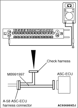
(1)Disconnect the ASC-ECU connector, connect special tool ASC check harness (MB991997) to
the harness-side connector, and then measure the resistance at the special tool connector side.
| note |
Do not connect the special tool ASC check harness (MB991997) to ASC-ECU.
|
(2)Resistance between the terminal No.16 and the body earth, and between the terminal
No.47 and the body earth.
OK: Continuity exists (2 Ω or less)
Q.
Is the check result normal?
Go to Step 20.
An open circuit may be present in the earth circuit. Repair the wiring harness
between the A-58 ASC-ECU connector terminal No.16 and the body earth, and between the A-58 ASC-ECU
connector terminal No.47 and the body earth.
|
|
|
Q.
Is the communication with M.U.T.-III possible?
|
|
|
Replace the hydraulic unit (ASC-ECU) (Refer to ). Then
go to Step 21.
|
|
|
|
|
|
Intermittent malfunction (Refer to GROUP 00 - How to Cope with Intermittent
Malfunction .)
|
|
|
|
|
|
Q.
Is the communication with M.U.T.-III possible?
|
|
|
This diagnosis is complete.
|
|
|
|