|
|
- ASC-ECU contains the power supply circuit (terminal No.1) for the pump motor. The pump motor is energised by the motor switch, which is incorporated in ASC-ECU.
- The pump motor switch, which is incorporated in ASC-ECU, is always off unless the motor solenoid valve check is activated when the vehicle is started.
- ASC-ECU activates the pump motor by turning on the ECU built-in pump motor switch.
|
|
|
This diagnosis codes will be set under the cases below:
|
|
|
- When the power supply voltage of the pump motor, which is not in operation, is abnormally low for a prolonged period
- When the power supply voltage of the pump motor, which is not in operation, is abnormally high for a prolonged period
|
|
|
Current trouble
- Fusible link malfunction
- Damaged wiring harness and connectors
- Abnormality in battery or alternator
- ASC-ECU malfunction
|
|
|
Past trouble
- Carry out diagnosis with particular emphasis on wiring harness and connector failures between the power supply circuit (A-58 ASC-ECU connector terminal No.1) to the ASC-ECU motor and the earth circuit (A-58 ASC-ECU connector terminal No.16 and 47). For diagnosis procedures, refer to How to treat past trouble (GROUP 00 - How to Use Troubleshooting/Inspection Service Points
 ). ).
|
|
|
Use M.U.T.-III to diagnose the CAN bus lines.
|
|
|
Q.
Is the check result normal?
|
|
|
 Repair the CAN bus lines (Refer to GROUP 54C - CAN Bus Diagnosis table ). On completion, go to Step 2. Repair the CAN bus lines (Refer to GROUP 54C - CAN Bus Diagnosis table ). On completion, go to Step 2.
|
|
|
|
|
|
Q.
Is the diagnosis code No. C2116 set?
|
|
|
This diagnosis is complete.
|
|
|
|
|
|
Refer to GROUP 54A - Battery Test .
|
|
|
Q.
Is the battery in good condition?
|
|
|
Replace the battery. Then go to Step 11.
|
|
|
|
|
|
Refer to GROUP 16 - Charging System <4A9>, <4B1>, <BWC>, <4B1-T/C>.
|
|
|
Q.
Is the charging system in good condition?
|
|
|
Repair or replace the charging system component(s). Then go to Step 11.
|
|
|
|
|
|
Q.
Is the check result normal?
|
|
|
NO  : Repair the defective connector. Then go to Step 11. : Repair the defective connector. Then go to Step 11.
|
|
|
|
|
|
Visually check for open circuit in the fusible link No.26.
|
|
|
Q.
Is the check result normal?
|

|
(1)Disconnect the ASC-ECU connector, connect special tool ASC check harness (MB991997) to the harness-side connector, and then measure the resistance at the special tool connector side.
| note |
Do not connect the special tool ASC check harness (MB991997) to ASC-ECU.
|
(2)Disconnect the fusible link No.26.
(3)Resistance between the terminal No.1 and the body earth.
OK: No continuity
Q.
Is the check result normal?
 Replace the fusible link No.26. Then go to Step 11. Replace the fusible link No.26. Then go to Step 11.
The short circuit may be present in the power supply circuit. Repair the wiring harness between the A-58 ASC-ECU connector terminal No.1 and the fusible link No.26, and then replace the fusible link No.26. Then go to Step 11.
|

|
(1)Disconnect the ASC-ECU connector, connect special tool ASC check harness (MB991997) to the harness-side connector, and then measure the voltage at the special tool connector side.
| note |
Do not connect the special tool ASC check harness (MB991997) to ASC-ECU.
|
(2)Measure the voltage between the terminal No.1 and the body earth.
OK: Approximately battery voltage
Q.
Is the check result normal?
Go to Step 9.
The open circuit may be present in the power supply circuit. Repair the wiring harness between the A-58 ASC-ECU connector terminal No.1 and the fusible link No.26. Then go to Step 11.
|
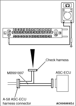
|
(1)Disconnect the ASC-ECU connector, connect special tool ASC check harness (MB991997) to the harness-side connector, and then measure the resistance at the special tool connector side.
| note |
Do not connect the special tool ASC check harness (MB991997) to ASC-ECU.
|
(2)Resistance between the terminal No.16 and the body earth, and between the terminal No.47 and the body earth.
OK: Continuity exists (2 Ω or less)
Q.
Is the check result normal?
Go to Step 10.
An open circuit may be present in the earth circuit. Repair the wiring harness between the A-58 ASC-ECU connector terminal No.16 and the body earth, and between the A-58 ASC-ECU connector terminal No.47 and the body earth. Then go to Step 11.
|
|
|
(1)Erase the diagnosis code.
|
|
|
(2)Drive the vehicle at 20 km/h or more.
| note |
The ABS warning lamp does not turn OFF in some cases unless the vehicle runs at 20 km/h or higher.
|
|
|
|
Q.
Is the diagnosis code No. C2116 set?
|
|
|
Replace the hydraulic unit (ASC-ECU) (Refer to ). Then go to Step 11.
|
|
|
|
|
|
Intermittent malfunction (Refer to GROUP 00 - How to Cope with Intermittent Malfunction ).
|
|
|
|
|
|
(1)Erase the diagnosis code.
|
|
|
(2)Drive the vehicle at 20 km/h or more.
| note |
The ABS warning lamp does not turn OFF in some cases unless the vehicle runs at 20 km/h or higher.
|
|
|
|
Q.
Is the diagnosis code No. C2116 set?
|
|
|
This diagnosis is complete.
|
|
|
|


