Pre-removal Operation
- Power Steering Fluid Draining (Refer to
 ). ).
- Engine Room Under Cover (Front, Rear) Removal (Refer to GROUP 51 - Under Cover ).
- Air Cleaner Cover and Air Intake Duct (A, B) and Intake Hose Assembly Removal (Refer
to GROUP 15 - Air Cleaner ).
- Radiator Hose (Lower, Upper) and Radiator Tank Removal (Refer to GROUP 14 - Radiator ).
- Engine Cover Removal (Refer to GROUP 11A - Engine Assembly <3800>,
GROUP 11C - Engine Assembly <3200>, GROUP
11E - Engine Assembly <3000>).
- Intercooler Assembly and Intercooler Hose (A1, A2, B) Removal (Refer to GROUP 15 - Intercooler ) <3200>.
|
Post-installation Operation
- Intercooler Assembly and Intercooler Hose (A1, A2, B) Installation (Refer
to GROUP 15 - Intercooler ) <3200>.
- Engine Cover Installation (Refer to GROUP 11A - Engine Assembly <3800>, GROUP
11C - Engine Assembly <3200>, GROUP
11E - Engine Assembly <3000>).
- Radiator Hose (Lower, Upper) and Radiator Tank Installation (Refer to GROUP 14 - Radiator ).
- Air Cleaner Cover and Air Intake Duct (A, B) and Intake Hose Assembly Installation
(Refer to GROUP 15 - Air Cleaner ).
- Engine Room Under Cover (Front, Rear) Installation (Refer to GROUP 51 - Under Cover ).
- Power Steering Fluid Refilling (Refer to ).
|
|
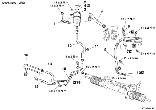
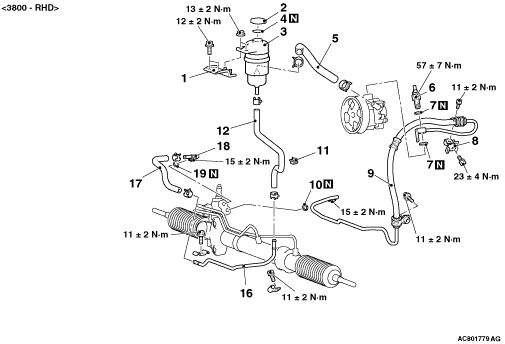
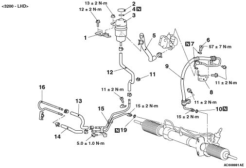
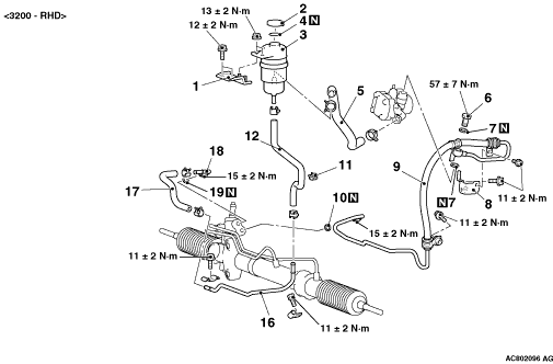
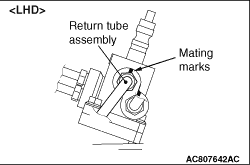
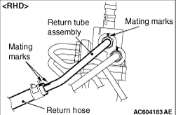
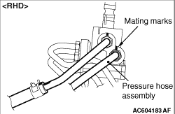
1.Align the mating marks on the gear box, return tube assembly and return hose when
installing.
2.Install the return hose and return tube assembly so that the mating marks are upward.<RHD>
|
|
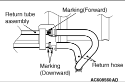
3.Install so that the markings are shown.
|
|
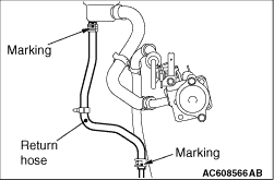
Install the return hose so that the markings and lines are faced rearward.
|
|
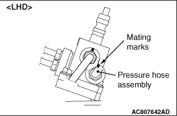
Align the mating marks on the gear box, pressure hose assembly when installing.
|
|
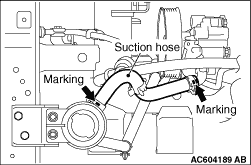
Install the suction hose so that the marking is positioned upward.
|