REMOVAL AND INSTALLATION


caution
  • Before removing the steering wheel, driver’s air bag module assembly and Knee Air Bag Module refer to GROUP 52B, Service Precautions , Driver’s Air Bag Module(s) and Clock Spring <Vehicles with SRS air bag> and Knee Air Bag Module . <Vehicles with knee air bag>
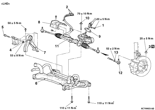
  • The parts indicated by * are the bolts with friction coefficient stabilizer. In removal, ensure there is no damage, clean dust and soiling from the bearing and thread surfaces, and tighten them to the specified torque.
Pre-removal operation
  • Steering Wheel Assembly and Driver’s Air Bag Module Removal (Refer to ).
  • Front Scuff Plate and Cowl Side Trim Removal (Refer to GROUP 52A - Interior Trim Removal and Installation ).
  • Heated Seat Switch, Shift Knob, Floor Console Panel Assembly Removal (Refer to GROUP 52A - Floor Console Assembly Removal and Installation ).
  • Inside Transmission Antenna Assembly (Front) Removal (Refer to GROUP 42B - Exterior Transmitter Antenna Assembly, Interior Transmitter Antenna Assembly, Receiver Antenna Module Removal and Installation ).
  • Floor Console and Floor Console Side Cover Removal (Refer to GROUP 52A - Floor Console Removal and Installation ).
  • Instrument Panel Cover Lower and Instrument Panel Lower Removal (Refer to GROUP 52A - Instrument Lower Panel Removal and Installation ).
  • Steering Shaft Cover Removal (Refer to ).
  • Engine Room Under Cover and Engine Room Side Cover Removal (Refer to GROUP 51 - Under Cover Removal and Installation ).
  • Lower Arm Removal (Refer to GROUP 33 - Lower Arm Removal and Installation ).
  • Stabilizer Link Removal (Refer to GROUP 33 - Stabilizer Bar Removal and Installation ).
  • Centremember and Front Roll Stopper Assembly Removal (Refer to GROUP 32 - Engine Roll Stopper and Centremember Removal and Installation ).

Post-installation operation
  • Centremember and Front Roll Stopper Assembly Installation (Refer to GROUP 32 - Engine Roll Stopper and Centremember Removal and Installation ).
  • Stabilizer Link Installation (Refer to GROUP 33 - Stabilizer Bar Removal and Installation ).
  • Lower Arm Installation (Refer to GROUP 33 - Lower Arm Removal and Installation ).
  • Engine Room Under Cover and Engine Room Side Cover Installation (Refer to GROUP 51 - Under Cover Removal and Installation ).
  • Steering Shaft Cover Installation (Refer to ).
  • Instrument Panel Cover Lower and Instrument Panel Lower Installation (Refer to GROUP 52A - Instrument Lower Panel Removal and Installation ).
  • Floor Console and Floor Console Side Cover Installation (Refer to GROUP 52A - Floor Console Removal and Installation ).
  • Inside Transmission Antenna Assembly (Front) Installation (Refer to GROUP 42B - Exterior Transmitter Antenna Assembly, Interior Transmitter Antenna Assembly, Receiver Antenna Module Removal and Installation ).
  • Heated Seat Switch, Shift Knob, Floor Console Panel Assembly Installation (Refer to GROUP 52A - Floor Console Assembly Removal and Installation ).
  • Front Scuff Plate and Cowl Side Trim Installation (Refer to GROUP 52A - Interior Trim Removal and Installation ).
  • Steering Wheel Assembly and Driver’s Air Bag Module Installation (Refer to ).
  • Wheel Alignment Check and Adjustment (Refer to GROUP 33 - On-vehicle Service - Front Wheel Alignment Check and Adjustment ).


Removal steps


1.
Steering column bolt (steering gear and steering column assembly connection)
<<A>>

2.
Electric power steering connector (in-vehicle electric power steering-ECU)
<<B>>

3.
self-locking nut (Tie-rod end and knuckle connection)


4.
Flange nut


5.
Rear roll stopper bolt
<<C>>

6.
Front axle crossmember


7.
Rear roll stopper


8.
Heat protector

>>B<<
9.
Steering column dash panel cover


10.
Steering gear bolt


11.
Steering gear and linkage assembly

>>A<<
12.
Tie-rod end

>>A<<
13.
Lock nut

REMOVAL SERVICE POINTS


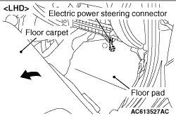
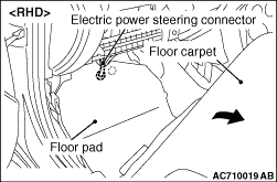
<<A>> ELECTRIC POWER STEERING DISCONNECTION


Peel off the floor carpet as shown in the figure. Remove the floor pad and then disconnect the electric power steering connector.

<<B>> SELF-LOCKING NUT (TIE-ROD END AND KNUCKLE CONNECTION) REMOVAL


caution
  • Do not remove the nut from ball joint. Loosen it and use the special tool to avoid possible damage to ball joint threads.
  • Hang the special tool with cord to prevent it from falling.

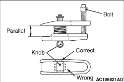
1.Install special tool ball joint remover (MB991897 or MB992011) as shown in the figure.

2.Turn the bolt and knob as necessary to make the jaws of special tool parallel, tighten the bolt by hand and confirm that the jaws are still parallel.
note When adjusting the jaws in parallel, make sure the knob is in the position shown in the figure.
3.Tighten the bolt with a wrench to disconnect the tie-rod end, lower arm ball joint.

<<C>> FRONT AXLE CROSSMEMBER REMOVAL


1.Support the crossmember, and remove it.
2.Check the hoses and harnesses for roughness, and then remove the front suspension crossmember with the rear roll stopper and the steering gear and linkage installed.

INSTALLATION SERVICE POINTS


>>A<< TIE-ROD END/LOCK NUT INSTALLATION


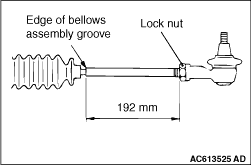
Screw in the tie-rod to the length shown in the figure, and hand-tighten the lock nut.
note Install the steering gear and linkage to the body, adjust the toe-in, and then tighten the lock nut to the specified torque.

>>B<< STEERING COLUMN DASH PANEL COVER INSTALLATION


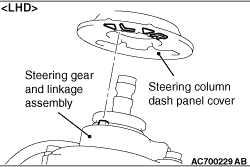
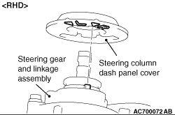
Install the joint cover grommet to the steering gear and linkage assembly by aligning L mark or R mark and the protrusion part of gearbox as shown in the figure.