REMOVAL AND INSTALLATION


Pre-removal and Post-installation Operations
  • Under Skid Plate, Engine Room Under Cover Front and Engine Room Under Cover Rear Removal and Installation (Refer to GROUP 51 - Under Cover ).
  • A/T Fluid Draining and Refilling (Refer to ).
  • Transfer Oil Draining and Refilling (Refer to ).
  • Front Exhaust Pipe, Front Catalytic Converter, Exhaust Support Bracket and Dash Panel Heat Protector Removal and Installation (Refer to GROUP 15 - Exhaust Pipe, Main Muffler and Catalytic Converter ).
  • Front and Rear Propeller Shaft Removal and Installation (Refer to GROUP 25 - Propeller Shaft ).
  • Radiator Condenser Tank Removal and Installation (Refer to GROUP 14 - Radiator ).
  • Air Intake Duct A Removal and Installation (Refer to GROUP 15 - Air Cleaner ).
  • Radiator Shroud Cover Removal and Installation (Refer to GROUP 14 - Radiator ).


Removal steps


1.
Tension wire connection


2.
Dynamic damper


3.
Tension wire


4.
Tension wire bracket


5.
Earth connection


6.
Transmission control cable connection


7.
Heater hose connection


8.
Starter motor


9.
Heat protector


10.
Oil level gauge assembly


11.
Bell housing cover

>>B<<
12.
Drive plate connecting bolts


13.
A/T fluid cooler pipe connection
<<A>>

14.
Transmission harness connector connection


·
Support the transmission with a transmission jack


15.
Transmission mount centre member assembly (Refer to GROUP 32 - Crossmember ).


16.
Transmission mount insulator assembly


17.
Transmission harness connection


18.
Breather hose connection

>>A<<
19.
Transmission upper connecting bolts

>>A<<
20.
Transmission lower connecting bolts
<<B>>

21.
Transmission assembly

REMOVAL SERVICE POINTS


<<A>> TRANSMISSION HARNESS CONNECTOR DISCONNECTION


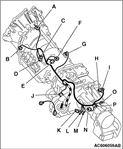
1.Lower the transmission to a position where the transmission harness connector can be disconnected, and then disconnect the connector.
2.Place the disconnected transmission harness so that it stays on the vehicle body.
Code
Connector name
A
Transmission wiring harness and battery wiring harness
B
Input shaft speed sensor
C
Oxygen sensor (left bank: rear)
D
Oxygen sensor (right bank: rear)
E
Inhibitor switch
F
A/T control solenoid valve assembly
G
Output shaft speed sensor
H
2WD operation detection switch
I
4LLc detection switch
J
Front propeller shaft speed sensor
K
Centre differential lock detection switch
L
4H detection switch
M
2WD/4WD detection switch
N
Shift actuator
O
Rear propeller shaft speed sensor
P
Vehicle speed sensor

<<B>> TRANSMISSION ASSEMBLY REMOVAL


caution 
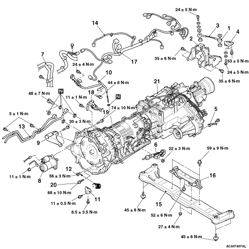
To prevent the engine assembly from tilting significantly when the transmission assembly is removed, place a piece of wood between the No.2 crossmember assembly and the oil pan to fix the engine assembly.

INSTALLATION SERVICE POINT


>>A<< TRANSMISSION UPPER CONNECTING BOLTS/TRANSMISSION LOWER CONNECTING BOLTS INSTALLATION


The sizes of the mounting bolts are different. So be sure not to confuse them.

Bolt
d × l mm
A
12 × 40
B
12 × 55

>>B<< DRIVE PLATE CONNECTING BOLTS INSTALLATION


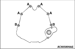
1.Temporarily tighten all the drive plate connecting bolts until bolt surfaces and the drive plate comes in full contact.
2.Tighten all the drive plate connecting bolts to the specified torque.
Tightening torque: 56 ± 3 N·m
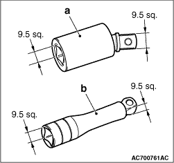
note The drive plate connecting bolt can be tightened to the specified torque easily by using the recommended tool [9.5 sq. flex ball joint (distributed by KTC, model number BJF20 <a in the figure>), or 9.5 sq. extension bar (swing head type) (distributed by KTC, model number BE3-030JW <b in the figure>) ].