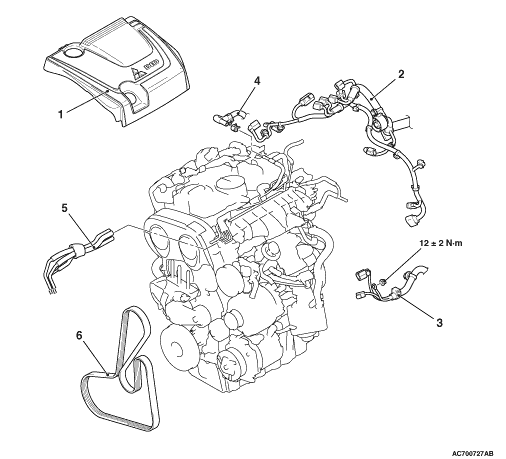
Pre-removal Operation
- Engine Room Under Cover Front A, B and Engine Room Side
Cover Removal (Refer to GROUP 51 - Under Cover
 ). ).
- Engine Oil Draining (Refer to GROUP 12 - On-vehicle Service, Engine Oil
Replacement ).
- Transmission Oil Draining (Refer to GROUP 22A - On-vehicle Service, Transmission
Oil Change ).
- Engine Coolant Draining (Refer to GROUP 14 - On-vehicle Service, Engine
Coolant Replacement ).
- Battery and Battery Tray Removal (Refer to GROUP 54A - Battery ).
- Air Cleaner Removal (Refer to GROUP 15 - Air Cleaner ).
- Catalytic Converter Removal (Refer to GROUP 17 - Catalytic Converter ). <Vehicles
without DPF>
- DPF Assembly Removal (Refer to GROUP 17 - Diesel Particulate Filter ). <Vehicles
with DPF>
- Intercooler Air Hose A, D, E, Pressure Hose Assembly and Air Pipe A, C, D Removal
(Refer to GROUP 15 - Intercooler ).
- Radiator Removal (Refer to GROUP 14 - Radiator ).
- Strut Tower Bar Removal (Refer to GROUP 42A - Strut Tower Bar ).
- Hood Removal (Refer to GROUP 42A - Hood ).
|
Post-installation Operation
- Radiator Installation (Refer to GROUP 14 - Radiator ).
- Intercooler Air Hose A, D, E, Pressure Hose Assembly and Air Pipe A, C, D Installation
(Refer to GROUP 15 - Intercooler ).
- Air Cleaner Installation (Refer to GROUP 15 - Air Cleaner ).
- Strut Tower Bar Installation (Refer to GROUP 42A - Strut Tower Bar ).
- Hood Installation (Refer to GROUP 42A - Hood ).
- Catalytic Converter Removal (Refer to GROUP 17 - Catalytic Converter ). <Vehicles
without DPF>
- DPF Assembly Installation (Refer to GROUP 17 - Diesel Particulate Filter ). <Vehicles
with DPF>
- Battery and Battery Tray Installation (Refer to GROUP 54A - Battery ).
- Engine Coolant Refilling (Refer to GROUP 14 - On-vehicle Service, Engine
Coolant Replacement ).
- Transmission Oil Refilling (Refer to GROUP 22A - On-vehicle Service, Transmission
Oil Change ).
- Engine Oil Refilling (Refer to GROUP 12 - On-vehicle Service, Engine Oil
Replacement ).
- Drive Belt Tension Check (Refer to ).
- Fuel Leak Check
- Engine Room Under Cover Front A, B and Engine Room Side Cover Installation (Refer
to GROUP 51 - Under Cover ).
|
|
|
After removing the cowl top panel, attach a protection tape for the windshield on the
lower area of the windshield.
|
|
|
The following operations will be needed due to the introduction of the serpentine drive
system with the drive belt auto-tensioner.
|
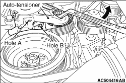
|
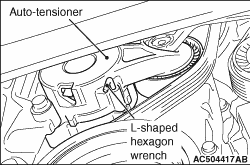
1.Rotate the auto-tensioner anti-clockwise and align hole A with hole B.
|
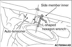
|
2.When inserting an L-shaped hexagon wrench, etc. into the hole of the auto-tensioner, insert
the wrench into the water draining hole of the side member inner first, and then insert it into
the hole of the auto-tensioner.
|
|
3.
| caution |
To reuse the drive belt, draw an arrow indicating the rotating
direction (clockwise) on the back of the belt using chalk, etc.
|
Insert an L-shaped hexagon wrench, etc. into the hole to fix the auto-tensioner and then
remove the drive belt.
|
|
|
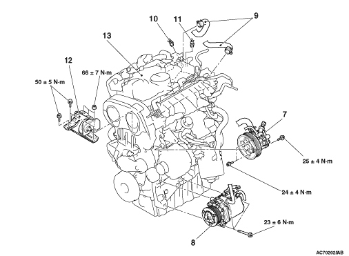
1.With the hose installed, remove the power steering oil pump from the bracket.
|
|
|
2.After removing the power steering oil pump, secure it with a cord in the location
where the removal and installation of the engine assembly cannot be hindered.
|
|
|
1.Remove the A/C compressor assembly together with the hose from the bracket.
|
|
|
2.Tie the removed A/C compressor assembly with a string at a position where
they will not interfere with the removal and installation of engine assembly.
|
|
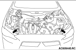
1.Install the front end upper bar bolts to the position as shown in the figure.
2.Remove the transmission assembly (Refer to GROUP 22A - Transmission Assembly ).
|
|
|
1.
| caution |
When supporting the engine assembly with a garage jack, be
careful not to deform the engine oil pan.
|
Place a garage jack against the engine oil pan with a piece of wood in between to support
the engine assembly.
|
|
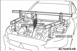
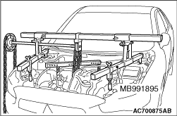
2.Remove special tools engine hanger (MB991928 or MB991895) which was installed for supporting
the engine assembly when the transmission assembly was removed (Refer to GROUP 22A - Transmission
Assembly ).
3.Operate a garage jack so that the engine weight is not applied to the engine mounting
insulator, and remove the engine mounting insulator.
|
|
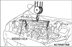
1.Install the special tool engine hanger balancer (MB991454) and set the chain block.
2.After checking that all cables, hoses and wiring harness connectors and so on are
disconnected from the engine, lift the engine assembly slowly with the chain block to remove the
engine assembly upward from the engine compartment.
|
|
Install the engine assembly, being careful not to pinch the cables, hoses, or wiring harness
connectors.
|
|
|
1.
| caution |
When supporting the engine and assembly with a garage jack,
be careful not to deform the engine oil pan.
|
Place a garage jack against the engine oil pan with a piece of wood in between, and install
the engine mounting insulator while adjusting the position of the engine assembly.
|
|
|
2.Remove special tool engine hanger balancer (MB991454).
|
|
3.Install special tools engine hanger (MB991928 or MB991895) which is used during installation
of transmission assembly to hold the engine assembly (Refer to GROUP 22A - Transmission
Assembly ).
4.Remove the garage jack which supports the engine assembly.
|
|
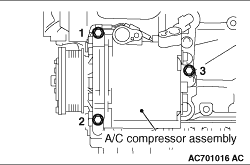
Tighten A/C compressor assembly mounting bolts to the specified torque in the
order of number shown in the illustration.
Tightening torque: 23 ± 6 N·m
|