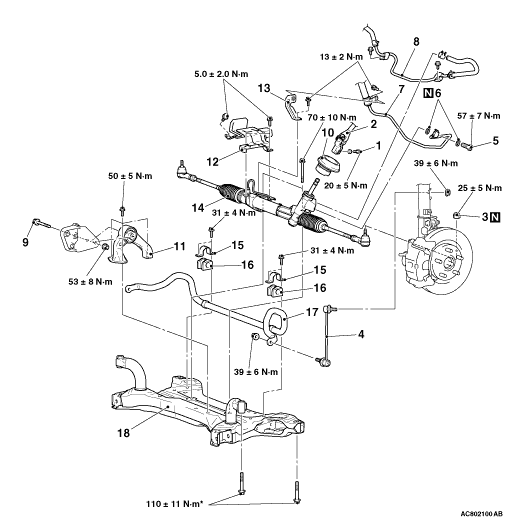
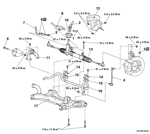
Pre-removal operation
- Steering Wheel and Air Bag Module Assembly Removal (Refer
to GROUP 37A - Steering Wheel
 ). ).
- Floor Console Side Cover Removal (Refer to GROUP 52A - Floor Console ).
- Footrest Removal.
- Cowl Side Trim (LH) Removal (Refer to GROUP 52A - Interior Trim ) <LH
drive vehicles>.
- Cowl Side Trim (RH) Removal (Refer to GROUP 52A - Interior Trim ) <RH
drive vehicles>.
- Turn up the driver’s side floor carpet.
- Steering Shaft Cover Removal (Refer to GROUP 37A - Steering Shaft ).
- Power Steering Fluid Draining (Refer to GROUP 37A - On-vehicle Service,
Power Steering Fluid Replacement ).
- Engine Room Under Cover A, B and Engine Room Side Cover Removal (Refer to GROUP
51 - Under Cover ).
- Centremember Removal (Refer to ).
- Lower Arm Assembly Removal (Refer to GROUP 33 - Lower Arm ).
|
Post-installation operation
- Using Your Fingers, Press The Tie-rod End Ball Joint
Dust Cover To Check for a Crack or Damage (Refer to GROUP 37A - On-vehicle Service,
Ball Joint Dust Cover Inspection ).
- Using Your Fingers, Press The Stabilizer Link Ball Joint Dust Cover To Check for
a Crack or Damage (Refer to GROUP 33 - On-vehicle Service, Lower Arm Ball Joint Dust
Cover Inspection ).
- Lower Arm Assembly Installation (Refer to GROUP 33 - Lower Arm ).
- Centremember Installation (Refer to ).
- Engine Room Under Cover A, B and Engine Room Side Cover Installation (Refer to GROUP
51 - Under Cover ).
- Steering Shaft Cover Installation (Refer to GROUP 37A - Steering Shaft ).
- Cowl Side Trim (LH) Installation (Refer to GROUP 52A - Interior Trim ) <LH
drive vehicles>.
- Cowl Side Trim (RH) Installation (Refer to GROUP 52A - Interior Trim ) <RH
drive vehicles>.
- Footrest Installation.
- Floor Console Side Cover Installation (Refer to GROUP 52A - Floor Console ).
- Clock Spring Centring (Refer to GROUP 52B - Driver’s Air Bag Module ).
- Steering Wheel and Air Bag Module Assembly Installation (Refer to GROUP 37A - Steering
Wheel ).
- Power Steering Fluid Refilling (Refer to GROUP 37A - On-vehicle Service,
Power Steering Fluid Replacement ).
- Power Steering Fluid Air Bleeding (Refer to GROUP 37A - On-vehicle Service,
Power Steering System Air Bleeding ).
- Steering wheel straight-ahead position check.
- Front Wheel Alignment Check and Adjustment (Refer to GROUP 33 - On-vehicle
Service, Front Wheel Alignment Check and Adjustment ).
- Steering Wheel Sensor Calibration (Refer to GROUP 35C - On-vehicle Service,
Steering Wheel Sensor Calibration ) <Vehicles
with ASC>.
|
|
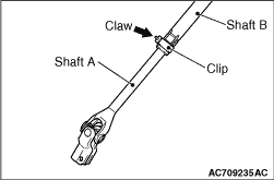
Disconnect the steering gear from the steering column assembly while sliding the shaft
A to the shaft B with the clip claw as shown in the figure is pinched.
|
|
| caution |
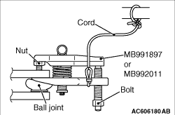
- Do not remove the nut from the ball joint, but only loosen it, and use the special tool.
- To prevent the special tool from dropping off, suspend it with a cord.
|
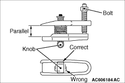
1.Install special tool ball joint remover (MB991897or MB992011) as shown in the figure.
|
|
2.Turn the bolt and knob to make the special tool jaws parallel, then hand-tighten the bolt.
After tightening, check that the jaws are still parallel.
| note |
To adjust the special tool jaws to be parallel, set the knob as shown in the figure so
that it functions as a fulcrum of the jaws.
|
3.Turn the bolt and disconnect the tie-rod end from the steering knuckle.
|
|
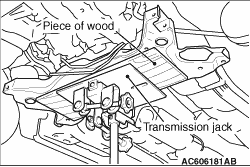
1.Jack up and support the crossmember, remove the crossmember mounting bolt.
2.Check the hoses and harnesses for roughness, and then remove the front axle crossmember
assembly with the rear roll stopper and the steering gear and linkage installed.
|
|
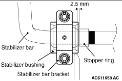
1.Install the stabilizer bar as shown in the figure.
|
|
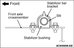
2.Install the stabilizer bushing as shown in the figure.
|
|
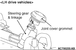
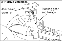
Install the joint cover grommet by aligning the projection of the steering gear and linkage
assembly with the mating mark of the joint cover grommet as shown in the figure.
|
|
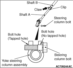
1.Pinch the claw of the clip shown in the figure. While sliding shaft A from shaft B, connect
the steering column shaft assembly with the steering gear and linkage assembly.
2.Insert the steering column bolt into the no-tapped bolt hole, and tighten it to the
specified torque.
Tightening torque: 20 ± 5 N·m
|